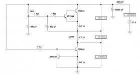
Hi John. The schematic you just posted doesn't appear to correspond to the one posted by euro21. The first and second pair of devices are a ZTX849 into a MJE15032 or 2ST1480FP. In your schematic, you show a ZTX849 into another ZTX849. Is this a different version?
That description is very different from the schematic I got. Is there a another different link/ I'll have a look.
")
i used two 24v/12VA transformers for one supply and a single 24+24v/25VA for another. In one supply I used a couple of Hammond 158T chokes in CLC which gave me 15.5v out, and I used a different operating point for the 01A. in the other I used a much larger choke with less DCR and that gave me a higher output voltage - may have been choke input or a very small cap. Didn't write it down.
Thanks!
That description is very different from the schematic I got. Is there a another different link/ I'll have a look.
The schematic that euro21 linked is not the one that I thought it was. My bad.
Rod wrote about this type of regulator here:
https://www.diyaudio.com/forums/tubes-valves/190857-4p1l-dht-line-stage-2.html#post2607592
https://www.diyaudio.com/forums/tubes-valves/190857-4p1l-dht-line-stage-2.html#post2607592
from 2004 to 2010 I did post quite a few circuits as design ideas - some with more or less errors. Since they appeared, the regulator kits are based on a properly designed and tested circuits, that are practical to use: adjustable, temperature-compensated, much lower noise, controlled-startup.
Tiz: constructors here use Filament Bias, because it allows the circuit to be built without cathode capacitors. With Filament Bias, the grid can be at ground, and the cathode has a low-value resistor - low enough that bypassing can be avoided. Sensitivity to capacitors seems to be very personal, to say the least, but at least this way you can compare the sound without caps in either position.
Of course, preamp filament bias must be run with the quietest possible current-feed. Bench supplies are unlikely to be good enough.
I would suggest using 20Ω (multiple resistors parallel, if it helps to get the value) filament bias resistor, and get about 5V bias. The bias voltage is not critical. And because the filament is thoriated tungsten, you can run it underheated somewhat, without shortening its life. This way, you can experiment with the filament regulator's trimmer to get different bias voltages, and add/remove paralleled resistors to change the 'range' of bias voltage. No need to rig up any test supplies - if you tested the regulator with a resistor, you can connect it to the filament with confidence.
Last edited:
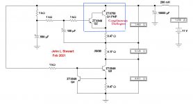
Bogus & an Alternative Version
Looks like Rod has given us a little more information.
Here is my pass on the original schematic I had.
And another version that looks the same on paper
but this time Q1 is a PNP transistor.
Looks like Rod has given us a little more information.
Here is my pass on the original schematic I had.
And another version that looks the same on paper
but this time Q1 is a PNP transistor.
Attachments
.from 2004 to 2010 I did post quite a few circuits as design ideas - some with more or less errors. Since they appeared, the regulator kits are based on a properly designed and tested circuits, that are practical to use: adjustable, temperature-compensated, much lower noise, controlled-startup.
Tiz: constructors here use Filament Bias, because it allows the circuit to be built without cathode capacitors. With Filament Bias, the grid can be at ground, and the cathode has a low-value resistor - low enough that bypassing can be avoided. Sensitivity to capacitors seems to be very personal, to say the least, but at least this way you can compare the sound without caps in either position.
Of course, preamp filament bias must be run with the quietest possible current-feed. Bench supplies are unlikely to be good enough.
I would suggest using 20Ω (multiple resistors parallel, if it helps to get the value) filament bias resistor, and get about 5V bias. The bias voltage is not critical. And because the filament is thoriated tungsten, you can run it underheated somewhat, without shortening its life. This way, you can experiment with the filament regulator's trimmer to get different bias voltages, and add/remove paralleled resistors to change the 'range' of bias voltage. No need to rig up any test supplies - if you tested the regulator with a resistor, you can connect it to the filament with confidence.
Thanks for the clarification Rod. I have put together the circuit I want to use on a breadboard, and am going to breadboard a quiet PSU to test it with shortly. For now I put a 1.2K resistor on the cathode of the 01A and a choke appropriate for the frequency response I need from the circuit on the plate of the 01A. I will try this first, and then try filament bias, Ale’s gyrator load, a CCS load etc. later on. Thanks for always being so helpful!
Last edited:
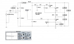
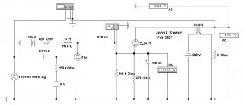
201A Filament Supply with AC Source Added, 1st Pass
This simple voltage doubler uses a common 6.3 Volt Heater Transformer.
A 12V transformer with a full bridge rectifier could also be used.
The ripple is about 4 mV p-p at the input to the Coleman Regulator.
More capacity would lower the ripple further.
This simple voltage doubler uses a common 6.3 Volt Heater Transformer.
A 12V transformer with a full bridge rectifier could also be used.
The ripple is about 4 mV p-p at the input to the Coleman Regulator.
More capacity would lower the ripple further.
Attachments
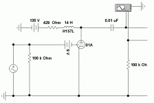
The 9V battery needs to apply -9V thru the grid resister to the grid. ....
Actually, a common way to do this was in SERIES with the grid. If the signal source had conductance (wound pickup, transformer) then no other resistor was needed. Mallory made button-size solder-in cells for the purpose.
But doesn't that kill the signal? No, the battery is <100r and the grid is >100Meg.
If using something bigger than a button, stray capacitance may matter.
Attachments
PRR,
Thanks for posting the schematic with a Series Battery for grid bias.
I have had trouble finding those who believe that works well.
I always use a grid stopper right at the socket's grid tab.
I have successfully used series battery bias for both the input tube(s), and for the output tube.
Like all circuits, it does have tradeoffs, but those tradeoffs ( + and -) were good for some of my amps.
I even remember an analog XY plotter that had vacuum tubes, signal choppers, and serial button cells. That was an interesting piece of engineering.
Last edited:
Actually, a common way to do this was in SERIES with the grid. If the signal source had conductance (wound pickup, transformer) then no other resistor was needed. Mallory made button-size solder-in cells for the purpose.
But doesn't that kill the signal? No, the battery is <100r and the grid is >100Meg.
If using something bigger than a button, stray capacitance may matter.
PRR: Is stray capacitance still a concern if the battery is positioned as it is in John's schematic?
Attachments
PRR,
Thanks for posting the schematic with a Series Battery for grid bias.
I have had trouble finding those who believe that works well.
I always use a grid stopper right at the socket's grid tab.
I have successfully used series battery bias for both the input tube(s), and for the output tube.
Like all circuits, it does have tradeoffs, but those tradeoffs ( + and -) were good for some of my amps.
Got some photos of those amps?
I even remember an analog XY plotter that had vacuum tubes, signal choppers, and serial button cells. That was an interesting piece of engineering.
Sounds like Moseley of LA, soon to be acquired by HP. For a while Francis Moseley was the 3rd largest shareholder of HP stock.
Actually, a common way to do this was in SERIES with the grid. If the signal source had conductance (wound pickup, transformer) then no other resistor was needed. Mallory made button-size solder-in cells for the purpose.
But doesn't that kill the signal? No, the battery is <100r and the grid is >100Meg.
If using something bigger than a button, stray capacitance may matter.
I wonder if anyone makes a clip type holder for one, two or three 2032 button cells, something that could be soldered into a circuit.
I have the circuit entirely bread-boarded and would like to test it. I have a couple of pairs of 01A tubes, and would like to test the circuit with the EL84 in it, and a dummy 01A before I put an actual 01A in it and apply the B+. I already have the appropriate resistors in place for the filament, and that is working properly as I confirmed it with an actual 01A installed (without B+). What would a dummy 01A load look like for the other two pins?
Other two pins Leave Open
The 01A Plate pin will simply go to B+. And the 01A Grid pin to the common thru the grid resister if no bias battery was inserted in that lead. Otherwise the bias battery voltage less some to cover the draw of the DMM, which usually looks like a 10 M resister to the point of measurement. Check those with your DMM.
You should see 5V across the 01A test resister. And from the simulations the 01A filament contact pins 1 & 4 will be at plus a few volts as we saw in the simulations. That due to the current in the 20R test resister.
All the other voltages should look normal, provided no wiring mistakes.
Here it is so far. Tube regulated power supply to the rear with added CLC filter in front of it. The breadboarded 01A/EL84 amp and the Coleman regulator and raw power supply to the left, with a Hammond 166L6 feeding the Coleman. Does Hammond make any power transformers that don’t have mechanical vibration? I have a couple that don’t, but they are ancient. The 166L6 makes the entire breadboard vibrate. I will have to move it off the breadboard for listening tests. Anyway, I’m going to add extra resistance inline to make sure my B+ isn’t too high for the 01A, and adjust the extra in order to get the correct B+ on the 01A plate. I’m shooting for 115-120V.
Attachments
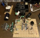
I wouldn't know. I have a 200v hammond power transformer that has an end bell that buzzes and annoys the crap out of me especially since it's on my hifi amp. I contacted them and they wanted me to mail it back. Rather than bother removing it from my completed amplifier, I decided to not buy hammond again after that. They're not worth the hassle. YMMV, bit I doubt it.
With an additional 20K of resistance added inline, the 01A has 104.5 Volts on the plate. Plate to cathode voltage is 96 Volts. The plate load is a a Hammond 157G (30H and 595 Ohms). This is with the 01A filament set to 200mA and 3.6 Volts with the Coleman filament regulator. There is a 2000 Ohm resistor biasing the cathode, and this resistor has 8.3 Volts dropped across it. This is a dissipation of .4 Watts, and 4.2 mA. How does this look so far?
The 01A has been running this way for about 20 minutes, and is still cool to the touch.
I forgot to hook up an RCA jack to the input at the pot. I will do this (along with moving the vibrating Hammond 166L6 away from the breadboard) and hook up a speaker next.
The 01A has been running this way for about 20 minutes, and is still cool to the touch.
I forgot to hook up an RCA jack to the input at the pot. I will do this (along with moving the vibrating Hammond 166L6 away from the breadboard) and hook up a speaker next.
Last edited:
- Home
- Amplifiers
- Tubes / Valves
- DHT driver for triode wired SE EL84, 6V6 or EL34