I have a Coleman regulator ready to go, so seems easy to try filament bias as well. There are so many different ways to go with biasing the 01A. Is there any reason why I can’t just add a LCLC at the output of the bench supply to get the ripple where I want it? The tube regulated bench supply is new to me and it would be convenient to use because it has variable B+ and a 6.3 filament output.
tizman,
Since you have installed socket for rectifier you can design a proper PS for your amp. You need not to worry about your bench PS or you may like to have some kind of regulator at the output of your bench supply.
Again as this is your first bear boarding project you may like to use 2700r 1/2 watt resistor for cathode bias + 220uf bypass cap. Once everything is up and running you may go for battery bias (everybody does not like battery bias sound though).
I am familiar with PSUDII and can put together a proper supply once I figure out which tubes I'm going to use and the voltages required. I would like to be able to use a variable voltage bench supply for bread-boarding so that I can vary voltages easily. I have the schematic for this supply somewhere. Once I find it, I can modify it so that it puts out cleaner B+ on its own, without having to put anything on the output to get the ripple down. Sounds like another thread actually.....
Last edited:
Dear tizman,
Important is Keeping it simple at initial power up.
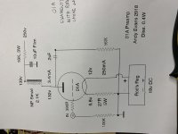
This is your wish DHT driver for el84/6v6 SE A1 output stage. Most important is simple implementation so that you have a taste of the sound signature. Afterwards, you can experiment with filament/RC/battery bias for the input tube, auto/fixed bias for the output tube etc.
you said your bench supply is giving out 1.5v ripple at its output. You may employ lclc/clclc/rcrc/crcrc and correct it. But this you can not use for the final build hence building a independent supply for bread-board is better. When you find time you may modify the bench supply and be done with that.
If I were you, I would do the following:
PT1
for B+(el84/6v6)andB++(01A) -may be 270 volt 200ma for pseudo choke input PS and
6.3 volt 2Amp min. for 2xel84/6v6 heaters
PT2
2x10 (separate supply for L/R channels) volt 2Amp min. for 2x01a filament-don't know colman reg requiremt it might be 15volt or so.
Resistor/choke loaded 01A, cathode bias with resistor plus bypass cap.
Cap coupled to self biased el84/6v6.
Once the system is up and running and stable with set bias points we will be teaming with you to complicate the circuit to suit your requirement and taste.
PLEASE NOTE HAVE DONE ALL POSSIBLE CONFIG for SE A1 OPS. After 20 years of musing with everything I have come back to the above and be done with that. That does not ensure it will match your test/requirement/room mode.
Until your bread-board is up and running you will not know anything no matter how smart our math is.
Important is Keeping it simple at initial power up.
This is your wish DHT driver for el84/6v6 SE A1 output stage. Most important is simple implementation so that you have a taste of the sound signature. Afterwards, you can experiment with filament/RC/battery bias for the input tube, auto/fixed bias for the output tube etc.
you said your bench supply is giving out 1.5v ripple at its output. You may employ lclc/clclc/rcrc/crcrc and correct it. But this you can not use for the final build hence building a independent supply for bread-board is better. When you find time you may modify the bench supply and be done with that.
If I were you, I would do the following:
PT1
for B+(el84/6v6)andB++(01A) -may be 270 volt 200ma for pseudo choke input PS and
6.3 volt 2Amp min. for 2xel84/6v6 heaters
PT2
2x10 (separate supply for L/R channels) volt 2Amp min. for 2x01a filament-don't know colman reg requiremt it might be 15volt or so.
Resistor/choke loaded 01A, cathode bias with resistor plus bypass cap.
Cap coupled to self biased el84/6v6.
Once the system is up and running and stable with set bias points we will be teaming with you to complicate the circuit to suit your requirement and taste.
PLEASE NOTE HAVE DONE ALL POSSIBLE CONFIG for SE A1 OPS. After 20 years of musing with everything I have come back to the above and be done with that. That does not ensure it will match your test/requirement/room mode.
Until your bread-board is up and running you will not know anything no matter how smart our math is.
I am sorry please read :
PT1
for B+(el84/6v6)and B++(01A) -may be 270 volt 200ma for pseudo choke input PS and
6.3 volt 2Amp min. for 2xel84/6v6 heaters
5.0 volt 3Amp for Rectifier
instead of
PT1
for B+(el84/6v6)andB++(01A) -may be 270 volt 200ma for pseudo choke input PS and
6.3 volt 2Amp min. for 2xel84/6v6 heaters
PT1
for B+(el84/6v6)and B++(01A) -may be 270 volt 200ma for pseudo choke input PS and
6.3 volt 2Amp min. for 2xel84/6v6 heaters
5.0 volt 3Amp for Rectifier
instead of
PT1
for B+(el84/6v6)andB++(01A) -may be 270 volt 200ma for pseudo choke input PS and
6.3 volt 2Amp min. for 2xel84/6v6 heaters
I have a Coleman regulator ready to go, so seems easy to try filament bias as well. There are so many different ways to go with biasing the 01A. Is there any reason why I can’t just add a LCLC at the output of the bench supply to get the ripple where I want it? The tube regulated bench supply is new to me and it would be convenient to use because it has variable B+ and a 6.3 filament output.
What kind of Reg PS is it? What are the published specs?
How many connexions does the Coleman device make to the audio circuit?
Couldn't find much on the iNet, least of all a circuit. From what I could read it sounds like its based on a switch mode circuit.
My own opinion, these 'Do It All' circuits that try to cover a wide variety of requirements are just as well left alone. Simple solutions are less likely to have problems. And involve a lot less parts.
I found a couple of interesting references to DC on the heaters of DH tubes. One makes a good case in favour of running current mode on the filament rather than constant voltage. But as usual, no experimental results to back that up.😱
DHT Heater Supplies Voltage Source vs Current Source Links
http://www.tentlabs.com/InfoSupport/page35/files/Heatingmethods.pdf
New DHT heater
http://www.tentlabs.com/InfoSupport/page35/files/Heatingmethods.pdf
Last edited:
minhaj: I have had a chance to go through all the advice and information so kindly provided by you all in this thread and and put together a plan. I will start simple and get it going shortly.
I'd use Rod Coleman's regs for any DHT, no question. But you do need to decide at the outset if you are going to use filament bias. The filament supply will need a higher voltage with filament bias. To keep it simple I'd make a filament supply in a separate box and use a 4 pin XLR as a connector. That way you can infinitely change the supply voltage without affecting the main chassis.
You could start with a simple circuit with a larger cathode resistor and bypass cap, but a good filament bias (and chokes are your friend here) will be worth the extra effort and planning. Small cathode resistor and no bypass cap. Rod can usually help with supply suggestions and voltages.
If you want to make a small investment, a couple of bench supplies like 30v at 2A or 15v at 4A are worth their weight in gold for these kind of experiments. Probably 30v at 2A is more versatile, especially with filament bias which may need as much as 20v or more.
Last edited:
How many connexions does the Coleman device make to the audio circuit?
Couldn't find much on the iNet, least of all a circuit. From what I could read it sounds like its based on a switch mode circuit.
[/URL]
See my post:
https://www.diyaudio.com/forums/tubes-valves/38248-dht-heater-96.html#post6507793
THX Euro21
I've printed that, I'll have a look tonite. Just cleaning up a dishwasher repair at home. Nothing works as well as it used to. Reliability of many useful items seems to have gone done the drain in recent years, And often impossible to get repair parts.🙂
I've printed that, I'll have a look tonite. Just cleaning up a dishwasher repair at home. Nothing works as well as it used to. Reliability of many useful items seems to have gone done the drain in recent years, And often impossible to get repair parts.🙂
John: So true. My dishwasher is the one that came with my house, which I bought 23 years ago. It was well used when we adopted it, and it’s still kicking.
I'd use Rod Coleman's regs for any DHT, no question. But you do need to decide at the outset if you are going to use filament bias. The filament supply will need a higher voltage with filament bias. To keep it simple I'd make a filament supply in a separate box and use a 4 pin XLR as a connector. That way you can infinitely change the supply voltage without affecting the main chassis.
You could start with a simple circuit with a larger cathode resistor and bypass cap, but a good filament bias (and chokes are your friend here) will be worth the extra effort and planning. Small cathode resistor and no bypass cap. Rod can usually help with supply suggestions and voltages.
If you want to make a small investment, a couple of bench supplies like 30v at 2A or 15v at 4A are worth their weight in gold for these kind of experiments. Probably 30v at 2A is more versatile, especially with filament bias which may need as much as 20v or more.
Andyjevans: As per the photo of your 2018 01A preamp circuit attached, what is the output voltage of the power transformer used? I’m using Coleman’s raw supply PCB, and I used 35 Volt capacitors when I built it in order to be able to use filament bias if I decided to.
Andyjevans: As per the photo of your 2018 01A preamp circuit attached, what is the output voltage of the power transformer used? I’m using Coleman’s raw supply PCB, and I used 35 Volt capacitors when I built it in order to be able to use filament bias if I decided to.
i used two 24v/12VA transformers for one supply and a single 24+24v/25VA for another. In one supply I used a couple of Hammond 158T chokes in CLC which gave me 15.5v out, and I used a different operating point for the 01A. in the other I used a much larger choke with less DCR and that gave me a higher output voltage - may have been choke input or a very small cap. Didn't write it down.
Do not pay any attention to those Dishwasher Detergent advertisements that say they clean the large food particles off your dishes.
They either own stock in Dishwasher companies, or they are receiving a kick back from them.
Large food particles will eventually make the dishwasher pump fail.
Clean the particles off the dishes first; then put them in the dishwasher to sterilize them.
Do the work up-front, or work later, to pay for a repaired or new dishwasher.
The circuit as shewn will not work
But easy to fix. The schema has Q1 & Q2 wrong way around. Q2 is holding Q1 off. So a simple rearrangement into the Darlington connexion is the fix.
But will still need another circuit for the 40V or more required for the 300B bias.🙂
But easy to fix. The schema has Q1 & Q2 wrong way around. Q2 is holding Q1 off. So a simple rearrangement into the Darlington connexion is the fix.
But will still need another circuit for the 40V or more required for the 300B bias.🙂
Attachments
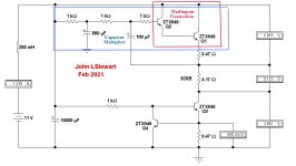
Hi John. The schematic you just posted doesn't appear to correspond to the one posted by euro21. The first and second pair of devices are a ZTX849 into a MJE15032 or 2ST1480FP. In your schematic, you show a ZTX849 into another ZTX849. Is this a different version?
Sorry. Here it is.
Looks like that won't take a rocket scientist (Werner von Braun, anyone?) or a Hotshot Double E to hookup. Beware of ground loops, the supply for the regulator is traveling a different path than the rest of your circuit. Can create some nasty results.😱
Try the Coleman circuit hooked up to your 01A while standing alone.
If you have a way to apply the power slowly, do that.
Or check the Coleman on a 20R resister, (sub for the 01A) then check the resulting voltages with your DMM.🙂
I tested the Coleman filament regulator on a resistor, and it works well. I haven't tried it on a 01A yet, but I will soon.
Hi John. The schematic you just posted doesn't appear to correspond to the one posted by euro21. The first and second pair of devices are a ZTX849 into a MJE15032 or 2ST1480FP. In your schematic, you show a ZTX849 into another ZTX849. Is this a different version?
Open the link in euro21s post. The schematic indicates the schema to be the 2010-7 model. As is it won't fly. But could if QI was a PNP transistor, then inverted. A common connexion in many SS output sections.🙂
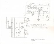
I've used that hookup, the advantage there is only one base-emitter junction to drift with temperature. Here it is in a piece of test equipment, a variable CC source. I've used this box a lot, real handy for testing low resistance in transformers & chokes. And SS diodes.
Attachments

- Home
- Amplifiers
- Tubes / Valves
- DHT driver for triode wired SE EL84, 6V6 or EL34