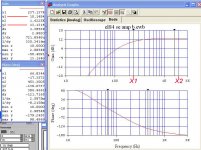
That would put the response 3db down at the specified frequency (500 Hz). If you would like to keep more of the signal at that frequency the choke needs to be a bit larger. 5H would probably be OK. But the RC coupling between the toobz needs to rolloff much lower than that. Same for the OPT.
If the OPT is also down that much the choke should probably be larger. Don't want too much attenuation at 500 Hz, could happen if the choke & OPT roll off at the same place. What OPT did you settle on? If you've got some specs, I'll do the calcs.🙂
All's well here, I'd planned to build a PP 6EA7 amp. But lots of snow to push around & things to fix in the house. The backup generator wouldn't start, I ended up getting a replacement carb from a US supplier. And I bought an Autel auto analyzer, the instruction manual was missing some critical steps. Lots of frustration.😱
I'm glad to hear you are doing well and keeping busy. Thanks for the help with this! The output transformers I want to use are small, very inexpensive units I found on Aliexpress. They cost $41 for one pair, and $44 for the other pair, delivered. They are advertised as being segmented and interleaved.
One pair has the following specs...
3 Watts
8K:4/8 Ohms
Primary current: 30mA
Primary inductance: about 12H
Primary copper resistance: 402Ω
Secondary copper resistance: 1.1Ω (8Ω)
Secondary inductance: 270mH
The second pair has fewer specs...
3 Watts
5K:4/8 Ohms
Primary inductance: 12H
Primary DC Resistance: 315Ω
My actual crossover is at 630 HZ. I used 500 HZ as a target to give me some margin in case I want to use this amp with a different HF section, a different two way, or change the crossover point to a lower one.
I asked about using a lower Henry choke as a plate load for the 01A because I have a couple of pairs of Hammond chokes handy. They are the Hammond 157G and 157L. Using a plate load for the 01A will mean that I can only use the amp as a treble amp, but I may put in a switch so that I can pick between a CCS or resistor and the choke.
157G:
30H
40 ma
595 Ohms resistance
400 Volts maximum
157L
14H
75 ma
429 Ohms resistance
400 Volts maximum
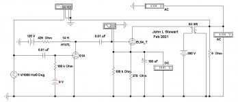
I have a 01A to 6V6 amp ready to be breadboarded, but also want to try an EL84. I would like to use the 6V6 or EL84 triode strapped. I also want to try a 26 as a driver, and possibly a 31 or 71A. If I get 1 clean watt out of the amp from about 500 HZ and up, that will be plenty for my HF horn.
Last edited:
Thanks for the suggestion. Unfortunately, I don't have any UL SE OPTs.
I generally just use junkbox parts, especially transformers. In this case I've got some Voice of Music OTs but the amp is sounding so nice I may order some Edcors for it and they do, as I recall, have UL taps.
As an update, I'm trying a few different DHTs as inputs. Got some 864s in there now and I'll be trying the 01A this weekend.
I'm really liking the concept of DHT input and IDHT output. These 6N6Gs are pretty amazing.
I've added a link to the "data" for the 6B5, which is an earlier version of the 6N6G with a different pinout. Probably the most detailed technical info I've ever seen on a tube. Almost all of it is way over my head, but you might find it interesting. It's really a marketing argument by the company that invented it as much as it is a data sheet.
https://tube-data.com/sheets/201/6/6B5.pdf
Both 3A5 & 3B7 were meant for operation at RF in applications such as RadioSondes (Weather Balloons). The curves don't look good for fidelity. Both now rare, many collectors look for samples for their stash. And some to build into odd amplifiers.
Anybody got one?🙂
I don't think the 3A5, 3B7 or 2C22 are particularly rare. They seem to be available and they're not expensive. I don't have any 3B7s but I picked up some 3A5s ($6) and 2C22s ($7) from the big dealer near me some years ago. All of the 2C22 / 7193 I've seen are JAN from WWII. I used four 2C22s in a PP 6B4G amp I built years ago. There is also a Russian version of the 2C22 it seems.2C22 is meant for HF transmission line amplifiers & oscillators up to 300 MHz. Thats why the anode & grid are brought out thru the top, thus avoiding long leads.
But a 6C5 or 6J5 is a lot easier to find, they are 1/2 a 6SN7. If stereo, just use a 6SN7. Anybody out there got a 2C22? Must be rare, they were never common.🙂
The 3A5 is still on my "need to try" list and, since they're 7 pin minis, I've thought it would be cool to use one with a SE 6AQ5.
It's always interesting to hear from someone who knows what these devices were actually designed for!
Attachments
Last edited:
I wouldn't bother with 3B7 - tried it and it never sounded good. 3a5 sounds OK but not special and would only be interesting for its rather higher mu of around 15. But maybe worth a whirl - long time since I tried it so I'm just going from memory. 2C22 is very good, though not a DHT.
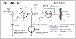
6N6G Etc
Charlie, you might find this interesting. I didn't have any of those weird toobz from the 30s & 40s, so I rolled my own. Here are some bench tests of a faux 6N6G, formed by a 6SN7 & 6F6. Did it work? Damned right!😀
Charlie, you might find this interesting. I didn't have any of those weird toobz from the 30s & 40s, so I rolled my own. Here are some bench tests of a faux 6N6G, formed by a 6SN7 & 6F6. Did it work? Damned right!😀
Attachments
Thanks for the additional info, John. I was aware that the combination of the 76 and 6AC5 could be used to mimic the 6N6G. It hadn't occurred to me that a pentode like the 6F6 could be used in triode mode. It's nice to have the two triodes contained in a single bottle, of course, but those are all great alternatives.Charlie, you might find this interesting. I didn't have any of those weird toobz from the 30s & 40s, so I rolled my own. Here are some bench tests of a faux 6N6G, formed by a 6SN7 & 6F6. Did it work? Damned right!😀
A few questions . . . In one of the attached documents you said, "most power pentodes when run as triodes with G1 & G2 strapped together have quite a high mu."
I've only seen triode strapped pentodes with G2 connected to the plate, typically with a 100 ohm resistor. Is this a misprint or can G2 be connected to G1 also? If so, I assume no resistor is necessary. Correct?
Does connecting G1 & G2 result in higher mu than with a G2 & Plate connection? If so, then a pentode could effectively be used to produce 3 different levels of mu, depending on how it's wired, not just 2.
And, you mentioned that the plate of the input triode can be connected to B+, as I did, or to an UL tap, as you suggested, but you also mentioned it could be connected directly to the plate of the output triode. What advantage is there to connecting the input plate to either an UL tap or the plate of the output section? Are there any disadvantages to either method?
Also, I was aware of the 25B5 and 25N6G but I had never looked at their data sheets. Oddly, while the 6N6G has a max plate voltage of 325v, the 25N6G has a maximum of only 180v. Any idea why? I would have expected them to be the same except for the heater.
As you point out, the base of the 6N6G is the same as many common power tubes. I recently modded a Magnavox PP 6V6 amp to use 6N6Gs with excellent results. Here's a link to that build. It's ugly but it sounds great. If I had known it was going to sound so good I would have gussied it up.
Magnavox 175/185 Build . . . With a Twist | Audiokarma Home Audio Stereo Discussion Forums
Last edited:
Where is tizman. Any progress from his side?
I’m here! I am moving forward slowly with breadboarding a 01A and 6V6 combo. I found out last night that the newly adopted regulated bench supply that I wanted to use for my breadboarding has 1.5 Volts of ripple on the DC output. Up to this point I have mostly built amps up on their intended chassis from already existing designs, or modified existing designs. Breadboarding is entirely new to me, and so are DHTs, so it’s going slowly. So far, I have built the breadboard with all its corresponding tube socket attachments, wired the 6V6 heaters, and built the Coleman regulator and its raw DC supply and tested it. Most of my time spent on this has been on researching the use of the 01A as a driver tube.
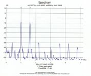
Clips at about 1.5 Watts.🙂
Thanks John. What is the value of the cathode bias resistor on the 01A in this schematic?
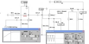
01A Biasing
For the simulation I used a fixed 9V Battery. So could for now use a 9V small battery for that. Easy to do, last as long as the shelf life of the battery.🙂
For the simulation I used a fixed 9V Battery. So could for now use a 9V small battery for that. Easy to do, last as long as the shelf life of the battery.🙂
For the simulation I used a fixed 9V Battery. So could for now use a 9V small battery for that. Easy to do, last as long as the shelf life of the battery.🙂
Is the 9 Volt battery supposed to be on the cathode of the 01A?
The 9V battery needs to apply -9V thru the grid resister to the grid. Ideally, no current ever flows from the battery. In real life, the battery would live for almost as long as if it sat on the shelf.
Some experimenters put the battery in the cathode circuit were it is continually charged while the cct is running. Most batteries don't like that, they need to be in a controlled charging cct where the current is held below some fraction of its capacity. Not a good place for a non-rechargeable battery at all.
Always better if the bias battery can be in the grid circuit, just like it was in ancient times when 01As were like flys.🙂
Attachments

Last edited:
As John says, it can be in the cathode, with the + to the pin and - to ground. But you need to use a rechargeable in that position. I ran 27s using a "9v" battery in cathode bias in an amp for quite a while with no problems as long as it was used regularly. If I used it sporadically, I would have to remove the battery and recharge it in a charger because it would lose it's charge.Is the 9 Volt battery supposed to be on the cathode of the 01A?
Recharging was a pain, so I switched it to battery grid bias, as shown in the schematic he posted and the one I posted earlier. With battery grid bias you connect - to the grid and + to ground. You also need to add a cap on the input to block DC.
I switched to using 01A in my amp yesterday. I'm using -4.5v on the grid which is provided by 3 AA alkaline batteries. I'd swap in some lithiums in a final build since their shelf life should be ~10 years. Plate voltage is 98v measured to ground. Plates are choke loaded using a Hammond 156c and voltage is regulated using a 0B2 regulator tube.
I used that operating point because the 0B2 needs a minimum current of 5mA and the data sheet lists a max plate voltage of 135v for the 01A. If I had stuck with my "9v" bias (actually ~9.78) and used a 0A2 regulator I might have been pushing it with both tubes. I used a 9v and a 0A2 with the 26s, as seen in my schematic.
The regular (non-rechargeable) AAs are about 1.5v each and a "9v" is usually somewhere around 9.45 to 9.8. Rechargeables measure a bit lower, AAs will be around 1.2v.
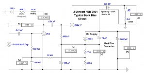
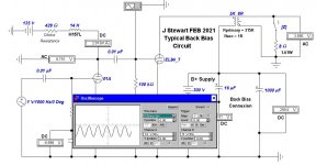
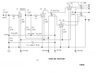
Front End Bias, No Batteries, No Diodes Fixed
All on the 01A EL84 Amp. using back biasing One volt on the front end drives the EL84 to clipping, see sine wave touches zero volts on the scope. Using the switch Z to open circuit the output allows a rough estimate of DF, looks like better than 2.
THX to Chris Hornbeck for pointing out my gross circuit error a couple of days ago. Thought I'd found a shortcut on the bias thing.🙂
Attachments
John and Charlie: Thanks for the explanation. I'm used to seeing bias on cathodes and it threw me off.
All on the 01A EL84 Amp. using back biasing One volt on the front end drives the EL84 to clipping, see sine wave touches zero volts on the scope. Using the switch Z to open circuit the output allows a rough estimate of DF, looks like better than 2.
Thanks for the schematic and fix. I will start with the EL84 instead of the 6V6, as I have all the requisite bits. How does this schematic fit in with the Rod Coleman filament regulator?
Last edited:
In general I've never used other people stuff, I like to grow my own. Sometimes I save a circuit for reference such as this time. I checked the thumb drive where I save that kind of thing & came up empty. Send a link or the schematic, I'll take a look.
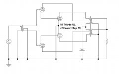
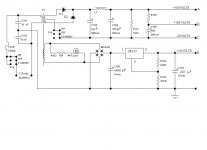
Attached how I did that on the PPUL 33 Amplifier. This one is also using back biasing. The performance is very good using such low powered 2Volt filament tubes.🙂
Attached how I did that on the PPUL 33 Amplifier. This one is also using back biasing. The performance is very good using such low powered 2Volt filament tubes.🙂
Attachments
John: I don't have a schematic for the Coleman regulator, but based on FlaCharlies schematic, which also uses battery grid bias, it appears to be a straightforward hookup. This is a link to his site and the regulator...
Rod Coleman DHT Filament Regulator
Rod Coleman DHT Filament Regulator
tizman,
Since you have installed socket for rectifier you can design a proper PS for your amp. You need not to worry about your bench PS or you may like to have some kind of regulator at the output of your bench supply.
Again as this is your first bear boarding project you may like to use 2700r 1/2 watt resistor for cathode bias + 220uf bypass cap. Once everything is up and running you may go for battery bias (everybody does not like battery bias sound though).
- Home
- Amplifiers
- Tubes / Valves
- DHT driver for triode wired SE EL84, 6V6 or EL34