minhaj: Not yet. I'm reorganizing my storage and work space at the moment, and working on getting an active crossover integrated with my two way horns. I'm also waiting for the delivery of the output transformers that I will be using in this build. This is the link for the thread I started about finding an appropriate OPT for this build...
Best OPT for use over 400 HZ
Best OPT for use over 400 HZ
Progress
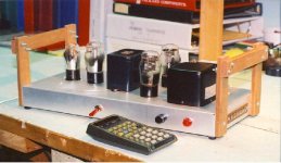
I have put together a breadboard, and a Coleman regulator and its DC supply. My first attempt will be a 01A driving a 6V6. I have a tube regulated bench power supply for the 6V6, but need to build the power supply for the 01A. I have a socket on the breadboard for a type 80 rectifier that I will use for the final power supply.
I have put together a breadboard, and a Coleman regulator and its DC supply. My first attempt will be a 01A driving a 6V6. I have a tube regulated bench power supply for the 6V6, but need to build the power supply for the 01A. I have a socket on the breadboard for a type 80 rectifier that I will use for the final power supply.
Attachments
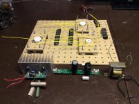
''I have a socket on the breadboard for a type 80 rectifier that I will use for the final power supply.''------?? Type 80 max current rating is 125ma as I remember. I never saw a tube rectifier is used for filament supply.
Regards
Regards
minhaj: the 80 rectifier is for the B+ of the 01A. I am going to use Rod Coleman’s regulator and raw B+!board for the 01A filaments. The 6V6 will use AC on the filaments.
Separate supply for 01A not needed in my opinion. If B+ supply for 6V6 is higher that 01A supply you may use RC filter from 6V6 B+ and done with that. However, this is your goat.....
Separate supply for 01A not needed in my opinion. If B+ supply for 6V6 is higher that 01A supply you may use RC filter from 6V6 B+ and done with that. However, this is your goat.....
minhaj: Sorry, my phone autocorrected your name to ninjas. I am wondering if I could use a plate choke for the 01A in this amp that has much less Henries than would normally be required because it will be a tweeter amp. Will it be possible to use a plate choke of 30 Henries if I will be using the amp only above 600 HZ?
I tried the 3A5 and the 3B7 as drivers for a 2A3 and vastly preferred the sound of a 12AT7 for whatever that might be worth to you. If you want to build something on a piece of plywood, a D cell battery is a decent filament supply for experimentation purposes.
Both 3A5 & 3B7 were meant for operation at RF in applications such as RadioSondes (Weather Balloons). The curves don't look good for fidelity. Both now rare, many collectors look for samples for their stash. And some to build into odd amplifiers.
Anybody got one?🙂
Attachments
If you don't hate tube top caps, 2C22 is an alternative solution.
2C22 is meant for HF transmission line amplifiers & oscillators up to 300 MHz. Thats why the anode & grid are brought out thru the top, thus avoiding long leads.
But a 6C5 or 6J5 is a lot easier to find, they are 1/2 a 6SN7. If stereo, just use a 6SN7. Anybody out there got a 2C22? Must be rare, they were never common.🙂
Attachments
Internal NFB
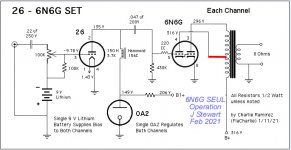
R25 & R34 are part of a NFB network formed by 25K (R24) in parallel with about 8K, the rp of the 26. Then that in series with 10K (R34), all that in parallel with 470K (R32).
So the 490K resister R25 is driving back into 15.53K. Not much NFB, just 15.53 / (15.53+ 490)
I'm curious..... what do resistors R25 and R34 add to the circuit?
R25 & R34 are part of a NFB network formed by 25K (R24) in parallel with about 8K, the rp of the 26. Then that in series with 10K (R34), all that in parallel with 470K (R32).
So the 490K resister R25 is driving back into 15.53K. Not much NFB, just 15.53 / (15.53+ 490)
Last edited:
71a as driver with EL84 SE is good 1.5W amp.
Sample: a little modified RH84
The EL84 in that example is running pentode. Tizman wants to run SET.😱
Required Choke for Rolloff Beginning a 400 Hz
Xl = 2(pi)fL At 3db down Xl = R
If f = 100 Hz, then L = R / (2(pi)f)
Taking R to be the rp of the driving triode to be say 8K & stuffing the numbers in
L = 8000 / (6.28 * 100)
L ~ 12.74 H
minhaj: Sorry, my phone autocorrected your name to ninjas. I am wondering if I could use a plate choke for the 01A in this amp that has much less Henries than would normally be required because it will be a tweeter amp. Will it be possible to use a plate choke of 30 Henries if I will be using the amp only above 600 HZ?
Xl = 2(pi)fL At 3db down Xl = R
If f = 100 Hz, then L = R / (2(pi)f)
Taking R to be the rp of the driving triode to be say 8K & stuffing the numbers in
L = 8000 / (6.28 * 100)
L ~ 12.74 H
Last edited:
Hi John! I hope you are doing well. Thanks for the equation.
The plate resistance of the 01A is 10000. I want to use this amp above 500 HZ. So...
L=10000/(6.28*500)
L=10000/3140
L~3.2 H
Just to clarify, does this mean that I can use a 3.2 Henry plate choke for the 01A, and that will give me 500 HZ to 20000 HZ 3 DB down?
The plate resistance of the 01A is 10000. I want to use this amp above 500 HZ. So...
L=10000/(6.28*500)
L=10000/3140
L~3.2 H
Just to clarify, does this mean that I can use a 3.2 Henry plate choke for the 01A, and that will give me 500 HZ to 20000 HZ 3 DB down?
Front End Bias, No Batteries, No Diodes
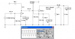
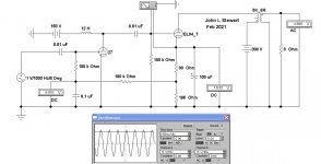
In the A cct front end ordinary cathode bias is used. In cct B the front end bias is obtained from the output tube thru an RC decoupling network. Not new, was often used in the 1930s receivers. Should work well with 1930s toobz.🙂
In the A cct front end ordinary cathode bias is used. In cct B the front end bias is obtained from the output tube thru an RC decoupling network. Not new, was often used in the 1930s receivers. Should work well with 1930s toobz.🙂
Attachments
Last edited:
Hi John! I hope you are doing well. Thanks for the equation.
The plate resistance of the 01A is 10000. I want to use this amp above 500 HZ. So...
L=10000/(6.28*500)
L=10000/3140
L~3.2 H
Just to clarify, does this mean that I can use a 3.2 Henry plate choke for the 01A, and that will give me 500 HZ to 20000 HZ 3 DB down?
That would put the response 3db down at the specified frequency (500 Hz). If you would like to keep more of the signal at that frequency the choke needs to be a bit larger. 5H would probably be OK. But the RC coupling between the toobz needs to rolloff much lower than that. Same for the OPT.
If the OPT is also down that much the choke should probably be larger. Don't want too much attenuation at 500 Hz, could happen if the choke & OPT roll off at the same place. What OPT did you settle on? If you've got some specs, I'll do the calcs.🙂
All's well here, I'd planned to build a PP 6EA7 amp. But lots of snow to push around & things to fix in the house. The backup generator wouldn't start, I ended up getting a replacement carb from a US supplier. And I bought an Autel auto analyzer, the instruction manual was missing some critical steps. Lots of frustration.😱
That's a lot of positive bias?
YOS,
Chris
You are absolutely correct Chris, I got it the wrong way round. I'll fix that on the morrow, it should be shewn as 'back bias'. Think I'm gettin' old.😱
PPUL 33s Driven by Triode connected 33
This one was built as a proof of concept about 20 yrs ago, it does work. Real well, in fact. The back bias network is R10, R11, R12 & C3. All of the amplifier B+ current passes thru that network on the way back to the PS on the -ve end.
The Electronic Workbench simulator does not respond to +ve bias values, otherwise that earlier sim I put up would have caught my silly mistake.
Attachments

- Home
- Amplifiers
- Tubes / Valves
- DHT driver for triode wired SE EL84, 6V6 or EL34