I guess it's the guitar folk that have their amps on their speaker cabinets that do the vast proportion of the whining. At that price, I could get a few spares.I haven't noticed more microphony with the 6J32P vs. old stock EF86s, and my sample size for each is well over 50 pieces.
I'll think about it for a while as I'm in no rush to buy these parts as I'm still waiting on the transformers to be built.
Input and phase split valves have arrived. Went NOS from langrex in the end. I may well get some 6J32p as spare/test devices still.
2x 6267/EF86 GE west german made
2x 5751 GE JAN USA made
Hopefully, the GZ34 and EL34's should be arriving tomorrow from hotrox along with some 30mm capacitor clamps.
2x 6267/EF86 GE west german made
2x 5751 GE JAN USA made
An externally hosted image should be here but it was not working when we last tested it.
Hopefully, the GZ34 and EL34's should be arriving tomorrow from hotrox along with some 30mm capacitor clamps.
The remainder of the valves arrived today.
4x matched Tung-Sol EL34B output valves
2x Sovtek 5AR4 rectifiers
I'm still waiting for modulus to ship the order for turret boards, turrets, noval sockets and some additional hookup wire. I've left ordering the remaining components from RS/Mouser until next month as there's not a lot I can do until the transformers arrive.
Something that I've been wondering about with regard to the layout is the positioning of the choke. Having watched some videos on the matter, it seems my positioning based on symmetry and the 5-10 may not be the best idea as it will sit directly above the turret board directly in between all of the valves. I assume it might be more sensible to position it next door to the mains transformer instead.
4x matched Tung-Sol EL34B output valves
2x Sovtek 5AR4 rectifiers
An externally hosted image should be here but it was not working when we last tested it.
I'm still waiting for modulus to ship the order for turret boards, turrets, noval sockets and some additional hookup wire. I've left ordering the remaining components from RS/Mouser until next month as there's not a lot I can do until the transformers arrive.
Something that I've been wondering about with regard to the layout is the positioning of the choke. Having watched some videos on the matter, it seems my positioning based on symmetry and the 5-10 may not be the best idea as it will sit directly above the turret board directly in between all of the valves. I assume it might be more sensible to position it next door to the mains transformer instead.
The Sovtek 5AR4 is an excellent value, but it can arc over (very bad) towards the top of the documented PIV range. Install the provided SS diode tweak and never look back. The "sand" provides some additional PIV headroom and puts the kibosh to arcing.
FWIW, I prefer UF4007s, instead of the 1N4007s shown. While the vacuum rectifier blocks SS diode switching noise, my thinking is that less switching noise, from the outset, can only help.
FWIW, I prefer UF4007s, instead of the 1N4007s shown. While the vacuum rectifier blocks SS diode switching noise, my thinking is that less switching noise, from the outset, can only help.
Attachments
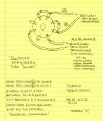
Thanks Eli, I've added some UF4007's to the shopping list for Mouser. I'll add it to the wiring diagram which I've just noticed had an error as my B+ was connected to pin 7 of the rectifier not pin 8.
For the money, and for "bullet proof" performance, I recommend uprating the parts... HER308 instead of UF4007 for instance...
That's fine with me. If it does the job well and is quiet. I'm happy.
I've been looking into the design further. The layout allows for both an even distribution of weight and symmetrical appearance along with the bonus of all the connections being on one side. However, The mullard 5-10 which I based the layout on doesn't have a choke. Is it considered unwise to mount the choke directly above the tag board? That would be on top of the aluminium chassis and the tag board on spacers underneath.
I've been looking into the design further. The layout allows for both an even distribution of weight and symmetrical appearance along with the bonus of all the connections being on one side. However, The mullard 5-10 which I based the layout on doesn't have a choke. Is it considered unwise to mount the choke directly above the tag board? That would be on top of the aluminium chassis and the tag board on spacers underneath.
Attachments

Last edited:
Mounting the choke above the tag strip should not be a problem. Just make sure the mains transformer, choke and output transformer windings are 90 degrees out from each other. I.e. make sure none of the windings are not in the same plane to keep the magnetic interaction to a minimum.
Since all of the transformers are stand mount EI core, I'm not 100% sure if that'll be easily possible if I mount all three on the top plate. I've got no idea which orientation the windings will be around the cores on each. I may have to wait until the transformers and chokes arrive before I make any firm decisions on placement/orientations.
Kei,
Do not worry about the power transformer and B+ choke magnetically coupling to each other. That is just a lesser issue.
If you ever use a choke input B+, the choke can really 'transmit' magnetically to the output transformers (chokes have air gaps).
Orient Both the power transformer and B+ choke the same.
Then Orient the output transformer(s) 90 degrees different than the way the power transformer and choke are oriented.
For any SE stereo amp, be sure the air gapped output transformers are not real close to each other, or there may be a little loss of stereo separation.
Push pull output transformers normally have all the E's and I's interleaved, and no air gap (or extremely small air gap). Push Pull transformers do not magnetically couple very much to each other, versus how SE transformers do.
Have fun building and listening.
Last edited:
The socalled "bell" side of the transformers radiate less magnetic field than the "plane field of the IE core". The closer the steel part of the IE is together the more impact there is.
You may want to power up the mains transformer (with some load, e.g. a light bulb) and then put a headphone on the primare of the OPT and listen to what the best orientation is but moving them around to each other.
I do not understand the fascination with chokes - with modern capacitors in decent sizes you can obtain similar levels of ripple control - I have been modelling a pSU for a SE and the difference is minimal. I'm talking here about 0.3V ripple on the output tubes B+ and 200uV ripple on the driver tubes part. Not worried about that.
Unfortunately a choke in DVD players / AD converters has been known to impact noise when close to certain other parts, I don't now the details about it and if it relates only to certain parts (wirewound resistors perhaps??).
The Leak 20 has the OPT and mains transformer almost touching each other but then that had a lot of NFB which was in vogue in those days. I like about 8 ~ 9db feedback, same as Claus Byrith (sound engineer in Denmark in classic music. Search for his name, Lundahl transformers and EL34. It has a suggested layout for your problem.)
Last but not least: I prefer to always check circuit diagrams in LtSpice. Recently came acorss a nice one ad when I checked it then it appeared that a resitor which would need to be 3.3K was shown as 33K (full stop was left out) making the NFB about 1.5 dB instead of 9 dB.
Attachments
For the money, and for "bullet proof" performance, I recommend uprating the parts... HER308 instead of UF4007 for instance...
Would 2-3 UF4007 in series be as good as I have several?
Thanks!
Randy
It's not the voltage rating but the current. UF5408 would do though. Chances are though, a 1A diode will be perfectly fine if you're not using giant caps in the power supply.
1 A. diodes are just fine! Remember, they are in series with a 5AR4 and the limits of the vacuum rectifier must be respected. A huge capacitance in the 1st filter position is not acceptable.
BTW, the 5AR4's slow start is protection against surge damage in the SS diodes. Synergy at its finest.
Thanks for this info, I'll stick with the current layout for now unless something makes it less feasible.Kei,
Do not worry about the power transformer and B+ choke magnetically coupling to each other. That is just a lesser issue.
If you ever use a choke input B+, the choke can really 'transmit' magnetically to the output transformers (chokes have air gaps).
Orient Both the power transformer and B+ choke the same.
Then Orient the output transformer(s) 90 degrees different than the way the power transformer and choke are oriented.
For any SE stereo amp, be sure the air gapped output transformers are not real close to each other, or there may be a little loss of stereo separation.
Push pull output transformers normally have all the E's and I's interleaved, and no air gap (or extremely small air gap). Push Pull transformers do not magnetically couple very much to each other, versus how SE transformers do.
Have fun building and listening.
I looked at the Claus Byrith design and I plan to potentially integrate some of his changes further down the road once I get the basic mullard design built and working.The socalled "bell" side of the transformers radiate less magnetic field than the "plane field of the IE core". The closer the steel part of the IE is together the more impact there is.
You may want to power up the mains transformer (with some load, e.g. a light bulb) and then put a headphone on the primare of the OPT and listen to what the best orientation is but moving them around to each other.
I do not understand the fascination with chokes - with modern capacitors in decent sizes you can obtain similar levels of ripple control - I have been modelling a pSU for a SE and the difference is minimal. I'm talking here about 0.3V ripple on the output tubes B+ and 200uV ripple on the driver tubes part. Not worried about that.
Unfortunately a choke in DVD players / AD converters has been known to impact noise when close to certain other parts, I don't now the details about it and if it relates only to certain parts (wirewound resistors perhaps??).
The Leak 20 has the OPT and mains transformer almost touching each other but then that had a lot of NFB which was in vogue in those days. I like about 8 ~ 9db feedback, same as Claus Byrith (sound engineer in Denmark in classic music. Search for his name, Lundahl transformers and EL34. It has a suggested layout for your problem.)
Last but not least: I prefer to always check circuit diagrams in LtSpice. Recently came acorss a nice one ad when I checked it then it appeared that a resitor which would need to be 3.3K was shown as 33K (full stop was left out) making the NFB about 1.5 dB instead of 9 dB.
Is the HER308 overkill for the application as my filter caps will be 10uF 600V MKP rather than the mullard design's 8uF electrolytic or PIO.1 A. diodes are just fine! Remember, they are in series with a 5AR4 and the limits of the vacuum rectifier must be respected. A huge capacitance in the 1st filter position is not acceptable.
BTW, the 5AR4's slow start is protection against surge damage in the SS diodes. Synergy at its finest.
Modulus parts arrived today, meaning all that's left is the main components and the transformers/choke.
4x Belton noval sockets
Assorted 22AWG hookup wire
2x 3mm turret boards
100x 3mm turrets
8x 30mm capacitor clamps
An externally hosted image should be here but it was not working when we last tested it.
I've done a quick layout test on a scale drawing which shows that I underestimated the space required between the capacitors.
An externally hosted image should be here but it was not working when we last tested it.
Since I'm drawing up the top panel design using front panel designer. Is it worth the extra expense to get the octal sockets drilled with ventilation holes? It adds between €10-30 depending on the size and number of holes.
Is the HER308 overkill for the application as my filter caps will be 10uF 600V MKP rather than the mullard design's 8uF electrolytic or PIO.
IMO, the 3 A. HER308 is unnecessary excess, in these circumstances. The continuous 1A. rated UF4007 is quite sufficient, given the continuous 250 mA. capability of the 5AR4/GZ34.
8 μF. was a large value, way back when. That is no longer the case. The previously linked 5AR4 datasheet shows as much as 60 μF. being safe. With those facts in mind, I'd lean towards Mouser stock # 647-UCY2H470MHD in the 1st filter position, providing 500 WVDC is adequate. Suppress as much ripple that safety allows, in that 1st position. Kept relatively cool, 105o C. rated 'lytics last a long time.
If I upped the capacitance of the first filter to 47uF, would an ntc inrush limiter be a smart addition or as you mentioned earlier, would the 5AR4 do that job? Would the other filters be fine remaining at 10uF?IMO, the 3 A. HER308 is unnecessary excess, in these circumstances. The continuous 1A. rated UF4007 is quite sufficient, given the continuous 250 mA. capability of the 5AR4/GZ34.
8 μF. was a large value, way back when. That is no longer the case. The previously linked 5AR4 datasheet shows as much as 60 μF. being safe. With those facts in mind, I'd lean towards Mouser stock # 647-UCY2H470MHD in the 1st filter position, providing 500 WVDC is adequate. Suppress as much ripple that safety allows, in that 1st position. Kept relatively cool, 105o C. rated 'lytics last a long time.
Essentially, so long as the ss diodes exceed the ratings of the tube rectifier, the tube will be protected by the ss diodes.Take 2 each 1kV diodes in series.
If one diode has far more reverse leakage current than the other diode, then most of the reverse voltage will be across the diode that has low leakage current.
Make sense?
I've spent some time checking the board layout against the original and the direction in which the connections face vs how I want to use them. Some tweaks later, almost all the connections now face the correct way around. I've increased the separation between C13/C14 & R20/R21 as they are 5W wirewound resistors so I've prefer to avoid cooking the capacitors. I've also considered the option of mounting them on the opposite side of the board so that the heat they generate rises into the metal top plate rather than directly through the turret board.
Shown in situ with the rest of the parts. I've incorporated the SS diodes on the rectifier socket but the value of C15 is still 10uF in the drawing. AC wiring will be twisted in reality. (Putting in twisted/curved wires into DIYLC slows it down to a crawl.)
An externally hosted image should be here but it was not working when we last tested it.
- Status
- This old topic is closed. If you want to reopen this topic, contact a moderator using the "Report Post" button.
- Home
- Amplifiers
- Tubes / Valves
- Planning first valve amp build