The first capacitor is 47uF and the datasheet for GZ34/5AR4 suggests a limit of 60uF, so it should be comfortably safe there. TBH, the 47uF capacitor and the SS diodes are the only real deviations in spec from the mullard design. (ignoring the layout changes)If you have a cap input B+, be sure to make the first one not too large.
Tube rectifiers like to arc at startup if the cap is too large.
Check the rectifier specs, especially since you have 410VAC.
The DC out is 1.414 x 410 minus the rectifier drop (small voltage drop on a 5AR4).
For a 5AR4 the data sheet recommends from 125 to 150 Ohms resistance (DCR of secondary, plus a resistor = 125 to 150 Ohms)
Choke input filter is different. 0.9 x VAC.
0.9 x 410V minus the rectifier drop. The rectifier drop is less on choke input, because of average current, versus peak current with cap input.
Easier current at start up for tube rectifiers.
No resistor needed.
I came up with a better design for the mounting of the capacitors. Using an L section of metal between the top surface and the capacitor allows two to be located along the side which will make the cables much shorter. The other two will remain on the back panel close to the HT transformer and rectifier. The approximate layout would be as shown except the IEC socket and two caps on the back panel will mount further down the side panel giving more space between them and the upper panel.
An externally hosted image should be here but it was not working when we last tested it.
I also finished constructing the first board all bar two capacitors. (one I forgot to buy and the other I've not yet mounted in the feedback path) I put R4/R15 onto the tag board to make cable routing easier as I had the space for it.
An externally hosted image should be here but it was not working when we last tested it.
I finally got a dispatch email for the HT transformers on Saturday, so I'm hoping that they arrive early this week.
One final question I have with respect to the value of the 180K resistors, R11/R12. In the build info, it suggests they should be matched within 5% with R12 having a greater value vs R11. I've got 1% metal film resistors that basically match. Three of them measure 179.0K and one was 179.1K. (which I've used in the R12 position for this board) How important is it that R12 is actually a bigger value?
There are a few specs that are inter-related:
The amount of the input capacitance (capacitive reactance)
Max peak current
Peak Voltage to the plate
5AR4 max peak current = 3.7 Amps
Consider the following, Peak Voltage/(Capacitive Reactance + DCR) has to be Equal or Less than the Max Peak current.
Vpeak/(Xc + DCR) =/< 3.7Amps
350VAC = 495V peak.
A 47uF cap is 28 Ohms capacitive reactance at full wave rectification of 120Hz (2 x line freq.)
i.e., 495V/(100 + 28 Ohms) = 3.87A peak.
That is over the max peak current of 3.7A.
100 Ohms DCR is not quite enough.
The only thing that may save the rectifier is that the filament and cathode warm up slowly. But if there are any areas of the cathode that are unevenly coated, then any 'high' spots are subject to sparking.
We like to see tubes glow, but we do not like to see arcing tubes.
I am just saying.
Last edited:
HT transformers turned up today. They look pretty well made. The mounting hole spacing doesn't quite match the datasheet even though all the other dimensions are correct.

Up against the choke on the planned layout. Coming together quite nicely.

Up against the choke on the planned layout. Coming together quite nicely.
Spent today making some L brackets to mount the capacitors and drill the holes to mount the HT transformer. The astute may notice that I've mounted everything upside down so the turret board connections are backwards. It's currently just a test fitting and simple to flip everything over to the opposite side of the board. It's provided a very useful guide to making sure I get the front panel design version correct for things like countersunk holes and any engravings. The L brackets were 30mm wide which I've decided is too tight for the nuts either side of the capacitors, so I've revised that up to 35mm.
Transformer in position.
Ironically, I've been working on a redesign as there would be rather a lot of empty space due to the capacitors now mounting on the inside of the chassis. In this version, the gap between the EF86 & ECC83 would be the only empty bit. I've got another spare piece of MDF like the one I've used, so I will probably build this one too. I've attached the FPD file from front panel designer.
For those without front panel designer software, this is the revised layout.
An externally hosted image should be here but it was not working when we last tested it.
Transformer in position.
An externally hosted image should be here but it was not working when we last tested it.
Ironically, I've been working on a redesign as there would be rather a lot of empty space due to the capacitors now mounting on the inside of the chassis. In this version, the gap between the EF86 & ECC83 would be the only empty bit. I've got another spare piece of MDF like the one I've used, so I will probably build this one too. I've attached the FPD file from front panel designer.
An externally hosted image should be here but it was not working when we last tested it.
For those without front panel designer software, this is the revised layout.
An externally hosted image should be here but it was not working when we last tested it.
Attachments
Last edited:
Thankfully, Sowter dispatched the output transformers yesterday which have just arrived today. I was very worried that these would not be turning up this side of summer due to the human malware issue. I've checked all the holes and thankfully they all line up nicely, so fitting to the test bed should be very easy provided I can find some suitable nuts/bolts.

Regarding some of the B+ voltage points above, I intend to run the transformer using the full 250V primary winding which should help to tame it as I've not seen our mains voltage exceed 240V yet. It seems to hover around 230-240V
Regarding some of the B+ voltage points above, I intend to run the transformer using the full 250V primary winding which should help to tame it as I've not seen our mains voltage exceed 240V yet. It seems to hover around 230-240V
Thankfully, Sowter dispatched the output transformers yesterday which have just arrived today. I was very worried that these would not be turning up this side of summer due to the human malware issue.
Hooray! Now you are in business. I was following (and enjoying) your thread and kept fingers crossed that those Sowters wouldn’t fall victim to Corona.
It was definitely one of those Phew! moments. Unfortunately, it's not quite there yet as I have some bits coming from RS that are needed in order to actually be able to fire one of these up to test.Hooray! Now you are in business. I was following (and enjoying) your thread and kept fingers crossed that those Sowters wouldn’t fall victim to Corona.
I found some suitable nuts, bolts and washers to fit the transformer to the wooden amp test build. Hopefully I'll construct the updated layout on another piece of MDF over the weekend.
An externally hosted image should be here but it was not working when we last tested it.
The more troublesome factor in all of this is that I was going to use Schaeffer AG to machine the aluminium top panels which is in Germany. I think it is unlikely to happen for quite some time.
How about copper or aluminum foil shielding tape on the non-metallic stuff you're currently building on? Some $ spent, but you buy plenty of time to get metal fabrication done.
Quite refreshing to see groups helping each other on this topic-
Long time blaster with my hard core solid state stuff... But have decided to build a class AB tube amp... just to see if it sounds as smooth as what I've been told.
Long time blaster with my hard core solid state stuff... But have decided to build a class AB tube amp... just to see if it sounds as smooth as what I've been told.
...
The more troublesome factor in all of this is that I was going to use Schaeffer AG to machine the aluminium top panels which is in Germany. I think it is unlikely to happen for quite some time.
I used Landfall Systems in the past who has 1/8" thick panels. He maybe can make only a top panel.
Since this is only a temporary test bed, I'm not sure it would be worth the expense. I'm in no rush to complete this but it would be nice to have all the bits gathered together so I have a quarantine hobby project that will help pass the time if things get more severeHow about copper or aluminum foil shielding tape on the non-metallic stuff you're currently building on? Some $ spent, but you buy plenty of time to get metal fabrication done.
Not a clue at this stage, but things are not moving as freely as they were before all this kicked off. Their site doesn't say anything to suggest they aren't operating as normal. I'm not likely to be ordering my panels until mid april at best, so there is always time for things to either improve or get worse.Is Schaeffer closed?
They are going to be a lot more expensive than Schaeffer based on what I could see and coming from the US, I expect the shipping would be pretty steep compared to Germany. They certainly look good though.I used Landfall Systems in the past who has 1/8" thick panels. He maybe can make only a top panel.
Remainder of the essential parts. Yet again I've slightly mucked up my order and only ordered 2 HT fuse holders instead of 4, so I have enough for one amp only, which isn't the end of the world.
2mm fibreglass sleeving in both red and black, which will be handy for some of the spaghetti.
30mm capacitor clamps that actually fit
Power switches, 5A/250VAC vandle proof push button on off switches (12V orange LED if I can be bothered to wire it up)
6.3x0.8mm JST flag crimps
M3 solder tags to help distribute the ground bus wire on standoffs
22nF MKP film capacitors (the bit I missed when I ordered the bulk of the components from mouser)

Technically, I'm still lacking high voltage rated barrier strips for the B+, 4mm banana sockets for the speaker binding posts, threaded insulated standoffs for the ground bus, lacing chord to help keep the looms neat and some 16 gauge tinned copper wire to use for the ground bus. (unless the 18 gauge I have is sufficient)
Spent several hours over the weekend making some supports for the base plate with all the necessary cutouts for fuses, sockets, switches and capacitors.

With all the transformers and the valves fitted. It's already a serious case of spaghetti inside and that's nowhere near all the wiring. 😱 I Think These may well be too narrow as it's seeming a bit snug on the inside, that said, these wooden blocks are impinging on the internal space where a mitred frame wouldn't.

In anodised/machined aluminium, I reckon this is going to look pretty good.

IMO, on this particular layout, the position of the on/off switch is too close to the output transformer. Moving the switch would make it seem illogically positioned.
With all the transformers and the valves fitted. It's already a serious case of spaghetti inside and that's nowhere near all the wiring. 😱 I Think These may well be too narrow as it's seeming a bit snug on the inside, that said, these wooden blocks are impinging on the internal space where a mitred frame wouldn't.
In anodised/machined aluminium, I reckon this is going to look pretty good.
IMO, on this particular layout, the position of the on/off switch is too close to the output transformer. Moving the switch would make it seem illogically positioned.
For those without front panel designer software, this is the revised layout.

Kei,
Is 'front panel designer' software same as CAD (Computer Aided Design) software? Capable of generating dxf or dwg 2D files that can be downloaded and directly used for cutter pathing with water jet or laser jet cutter?
Jim
Jim, front panel designer is indeed CAD software. (Can be downloaded free from front panel express or ag shaeffer) By default it creates it’s own format FPD files. Dxf files can be exported along with svg and pdf. I assume the dxf could be used for cutter pathing.
Jim, front panel designer is indeed CAD software. (Can be downloaded free from front panel express or ag shaeffer) By default it creates it’s own format FPD files. Dxf files can be exported along with svg and pdf. I assume the dxf could be used for cutter pathing.
Yes,
Here in US, dxf file can be directly loaded into cnc laser or water jet cutter at most facilities. I would think similar in UK. Should be able to have local cnc shops produce dxf designs from material of your choice.
Also,
If your 'spaghetti' wiring becomes a headache, then consider a DIY circuit board. I've used Fritzing with success. It's free download entry level stuff, but fun to learn. Of particular importance is that Fritzing can export G codes- which, like dxf, are industry standard.
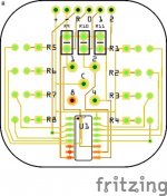
So you can export those to PC board house, there are some advertised here, that can produce your design. I've attached a screen shot of one of my Fritzing projects.
Jim
Attachments
I'm avoiding PCB's in this thing deliberately if I can as it's far easier to modify down the road without them. I'll see how things are in a few weeks time when I review what top panel design I decide to go with if it all pans out properly. I've got a sneaking suspicion that I may be making more design tweaks as it does seem a tad snug, which probably won't bode well for noise performance.
I've notched the central support to allow for the wiring to the EL34's and added a tag strip for the anode/UL connections from the output transformer. Will be looming the pairs together when I build it. I've also fitted the ground bus bar supports.
With the turret board in position. I'm not going to bother with the power switch for the time being as the position and the wiring to it is not easy to achieve. It's something I'll be looking into figuring out further down the road. The screwdriver bits mark the position of the ground bus wire.
I'll look at adding some small side panels on which will help to brace the end panels as well as allow mounting of the input socket. The MDF does have a moderate degree of flex when I lift it to move it around, which isn't a surprise considering this thing weighs nearly 12Kg.
I've notched the central support to allow for the wiring to the EL34's and added a tag strip for the anode/UL connections from the output transformer. Will be looming the pairs together when I build it. I've also fitted the ground bus bar supports.
An externally hosted image should be here but it was not working when we last tested it.
With the turret board in position. I'm not going to bother with the power switch for the time being as the position and the wiring to it is not easy to achieve. It's something I'll be looking into figuring out further down the road. The screwdriver bits mark the position of the ground bus wire.
An externally hosted image should be here but it was not working when we last tested it.
I'll look at adding some small side panels on which will help to brace the end panels as well as allow mounting of the input socket. The MDF does have a moderate degree of flex when I lift it to move it around, which isn't a surprise considering this thing weighs nearly 12Kg.
I'm avoiding PCB's in this thing deliberately if I can as it's far easier to modify down the road without them. I'll see how things are in a few weeks time when I review what top panel design I decide to go with if it all pans out properly. I've got a sneaking suspicion that I may be making more design tweaks as it does seem a tad snug, which probably won't bode well for noise performance.
Agreed,
Prototyping is experimental by nature. PC boards can clean things up after design is established- just an idea.
Will continue to follow progress.
Best,
Jim
Made a start on the wiring today. The grounds have been left loose for now as that's tomorrows job. Hopefully I'll be able to do a test run tomorrow and see what voltages are like. (sans tubes obviously at this stage) I've loomed the various wires together up the centre to try and keep things neat.
The HT and heater wiring around the rectifier is a tad messy as I really didn't want to cut the leads too tightly in case I need to alter the layout.
With the turret board in position.
An externally hosted image should be here but it was not working when we last tested it.
The HT and heater wiring around the rectifier is a tad messy as I really didn't want to cut the leads too tightly in case I need to alter the layout.
An externally hosted image should be here but it was not working when we last tested it.
With the turret board in position.
An externally hosted image should be here but it was not working when we last tested it.
Finished up the ground bus today and did a quick test run on the mains transformer with no valves in place to see what no load voltages I got.
HT - 414V
Heater 1 - 5.1V
Heater 2 - 3.18V
Heater 3 - 3.18V
Seems pretty close with no load so will probably be a tad low when loaded.
HT - 414V
Heater 1 - 5.1V
Heater 2 - 3.18V
Heater 3 - 3.18V
Seems pretty close with no load so will probably be a tad low when loaded.
- Home
- Amplifiers
- Tubes / Valves
- Planning first valve amp build