I do not understand the fascination with chokes - with modern capacitors in decent sizes you can obtain similar levels of ripple control - I have been modelling a pSU for a SE and the difference is minimal. I'm talking here about 0.3V ripple on the output tubes B+ and 200uV ripple on the driver tubes part. Not worried about that.
The OP is employing a 5AR4/GZ34 vacuum rectifier. A huge 1st filter capacitance to "gorilla stomp" ripple is not permitted.
Large 1st filter capacitances come with their own "baggage". Scan the archives for my posts about "hash" filters. An unwanted consequence of a huge 1st filter capacitance is the presence of ripple overtones extending well up into the RF range.
IMO, newer designs (both tube and SS) eschew inductors for reasons of space, weight, and especially cost.
Hi Eli, I suppose it is a matter of "it all depends".
I'm purely working in class A so can afford some resistance in the transformer - 1st capacitor stage and have only a 47uF as first one. But then after a 150 Ohm resistor I go up to 200uF. And a 1N4007 is not very pleasant to use, I've taken a liking to the BYW96E but am always looking for something better.
Chokes that go inside the chassis do not need to be expensive, it more a matter of how much weight and space I want to sacrifice.
But if you're working with PP and class AB2, or even B, then a choke becomes almost mandatory. BTW I'm not fond of an electronic choke.
A 5AR4 has 1500V Peak Inverse Voltage rating.
A 1N4007 has 1000V Peak Inverse Voltage rating.
Now, to take an extreme, put two 1N4007 diodes in series.
Suppose one has much much less reverse current at 1000V than the other diode.
Apply 1500V reverse voltage across the series pair. The leaky diode has 350V across it, and the low leakage diode has 1150V across it.
Probably will never happen, but a couple of different manufacturer's diodes out of a spare parts box may cause a problem.
Chokes arrived today. Still waiting on the rest of the transformers.
An externally hosted image should be here but it was not working when we last tested it.
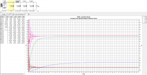
Having run some simulations for the power supply, I have some questions regarding the behaviour of a valve rectifier and inrush. The PSUD simulation shows a fairly hefty 4A spike right at switch on across the first capacitor. Does the valve essentially soften this due to it's slow starting nature?
Raising the Capacitance of the first capacitor has the effect of increasing the peak voltage seen on the second capacitor. 47uF in the C15 position (C1 in simulation) results in a spike of around 590V at the capacitor on C12. (C2 in simulation) Again, is this mitigated by the valve rectifier and not really a problem?
Lastly, is a 500V electrolytic capacitor at C15 adequately rated or should I aim for 600V? The simulation shows a peak of 436V.
Attachments
Lastly, is a 500V electrolytic capacitor at C15 adequately rated or should I aim for 600V? The simulation shows a peak of 436V.
A 500 V. rated part should be fine. Remember, the rating is for its working voltage. Provided it's not silly "tall", the part will withstand a brief, higher, turn on surge.
That suits me. I found an F&T 47uF 500V electrolytic which suits me perfectly as it's a decent size so I can utilise the mounting clips that I bought.A 500 V. rated part should be fine. Remember, the rating is for its working voltage. Provided it's not silly "tall", the part will withstand a brief, higher, turn on surge.
I've been trying to find some info on how a valve rectifier behaves at switch on from cold in order to understand how the voltages will behave but I'm finding it's not something I can find much info on. Plenty of info about internal resistance and sag.
Distinguish between directly heated types, such as the 5U4, and types with cathode sleeves, like the 5AR4/GZ34. The directly heated types start nearly as quickly as SS diodes do. OTOH, types with cathode sleeves start quite slowly. It's a matter of the amount of mass being raised to full emission temperature.
Vacuum diodes intended for damper service in TV sets are very slow starting. Examine the brutish 6CJ3's datasheet.
Vacuum diodes intended for damper service in TV sets are very slow starting. Examine the brutish 6CJ3's datasheet.
1. If you want to know what the required voltage is for each of your B+ electrolytics,
Then take out all your amplifier tubes other than the rectifier tube.
Watch the B+ rise to 1.414 X the secondary voltage with a bridge rectifier (or for full wave CT secondary, 1.414 x 1/2 the full secondary voltage).
1. A. Be careful!
Lock your DMM in its high range so it is not auto-ranging (and not keeping up).
Then watch the B+ rise as the tube rectifier warms up, and . . .
Get ready to "instantly" turn the power off before it exceeds the voltage you thought it would be (or the electrolytic voltage rating).
Surprise!
Instead, use method 2. and 3. below.
2. Do not try 1. above with solid state rectifiers or Directly Heated Rectifiers, the B+ comes up too quickly, use a variac instead, and slowly turn up the voltage. Stop when you get the B+ as high as you dare, then read the variac output voltage.
Suppose the variac goes to 100V, and the B+ is 500V. But you have 120V from the mains,
you need 120/100 x 500V = 600V electrolytics.
3. The variac method is also a safer way to test tube rectified B+ than the somewhat risky method 1. above.
In most CLCRC, LCRCRC, etc. B+ power supplies, I always use voltage ratings of ALL the electrolytics in the B+ chain.
When the output tubes die, the B+ goes way up. The last electrolytic in the filter, the one that runs the input tube, is now running at 550V, but I/you may have used one that was rated for 450V.
Example, you brought your amp over to a friends place for a shootout.
You plugged it in, and powered it up (oh, did you forget you took all the tubes out (except the tube rectifier if it has one) and packed them in their boxes for transport).
Sadly I don't have a variac. It's on the, to be obtained at some point list. They seem to be pretty pricey here in the UK. Buying one without an enclosure seems to be a lot cheaper until you add in all the bits that need to be bought to make it usable. I'm not sure I'd trust a cheap item bought from amazon.
I think I may be worrying over nothing as the mullard component sheet don't specify any components with a voltage rating above 500V.
I think I may be worrying over nothing as the mullard component sheet don't specify any components with a voltage rating above 500V.
Spent the weekend building a prototype top panel using a scrap of MDF to help prove the concept. Some small tweaks may be needed to the noval socket cut outs, but it seems to work quite well.
Didn't have any M2 bolts that were long enough to attach the turret board but it fits in place properly nonetheless.

With the valves fitted into the sockets. Still waiting on the other transformers. Will sort ordering the components this week to I can start to build the turret boards.

Should look pretty good in aluminium

Didn't have any M2 bolts that were long enough to attach the turret board but it fits in place properly nonetheless.
With the valves fitted into the sockets. Still waiting on the other transformers. Will sort ordering the components this week to I can start to build the turret boards.
Should look pretty good in aluminium

Rest of the parts arrived today. The main filtering capacitors have caused some annoyance as they didn't state anywhere in the datasheet that these were stud mounted. Still, not the end of the world and the main reason why I cobbled together a prototype on some scrap wood.

Ironically, the other problem I encountered is that the "30mm" capacitor clips are clearly not 30mm as they don't clamp onto the F&T caps which are definitely 30mm. It's close but roughly 1mm too big.

So with the above issues, I'll need to adjust the way the caps mount to the plate. I'm not sure I want 3 big M6 nuts sitting on the top surface as I get the feeling it'll look like a bodge. I'm thinking of mounting them to the sides using threaded inserts.
Ironically, the other problem I encountered is that the "30mm" capacitor clips are clearly not 30mm as they don't clamp onto the F&T caps which are definitely 30mm. It's close but roughly 1mm too big.
So with the above issues, I'll need to adjust the way the caps mount to the plate. I'm not sure I want 3 big M6 nuts sitting on the top surface as I get the feeling it'll look like a bodge. I'm thinking of mounting them to the sides using threaded inserts.
Last edited:
There are clamps that fit almost every cap size, without using electrical tape.
Get another clamp, or get another cap.
There are exceptions to finding something that fits, because:
"Standards are such a wonderful thing that every manufacturing company has their own" (own standard).
In my opinion:
Tape looks bad. A lot worse than the clamp itself.
I sometimes use an "oval" motor run cap for the input C of B+. The clamp is slightly large for the cap. I cut a piece of sheet metal (not as tall as the clamp), and hide it between the cap and the clamp (a small shim). Looks OK, except for the most picky who hover over the amp (I hope they do not burn their nose).
You might use the shim method for your round caps too.
If the caps are only rated for 85 degrees C, they will last a lot longer on the top of the chassis, even though the inside of the amp
never gets near 85 degrees C. Life of the cap is according to Time x Temperature. But keep the hot tubes away from the electrolytics.
PS from this threads earlier discussion:
To determine the maximum the B+ voltage when there is no load, assume zero volts drop in the rectifier, and multiply the center tapped half secondary voltage times 1.414.
Happy building, Happy listening
Last edited:
The big caps are indeed rated at 85 degrees. The unloaded voltage is a bit worrying as it's 410x1.414 which is just shy of 580V and that's if I get 410 out of the transformer. I'm praying I don't end up with it running higher than 410.If the caps are only rated for 85 degrees C, they will last a lot longer on the top of the chassis, even though the inside of the amp
never gets near 85 degrees C. Life of the cap is according to Time x Temperature. But keep the hot tubes away from the electrolytics.
PS from this threads earlier discussion:
To determine the maximum the B+ voltage when there is no load, assume zero volts drop in the rectifier, and multiply the center tapped half secondary voltage times 1.414.
Happy building, Happy listening
I've decided that the best approach due to the way the stud mounting caps look is to mount them inside the chassis, but away from the valves. Vertically mounting these outside the chassis would look a bit daft.
An externally hosted image should be here but it was not working when we last tested it.
All 4 capacitors will mount on the one side panel horizontally, underneath the HT transformer. The chassis side panels are going to be ~75mm high which seems to be sufficient to fit them in with decent breathing room. I'm looking at using threaded inserts into blind holes in order to mount them without having to use a nut on the outside of the chassis.
An externally hosted image should be here but it was not working when we last tested it.
I also laid the components out on the turret board to get a feel for the spacing and where the turrets will need to sit. It seems I may have room to spare. I left the two small pF caps out as they are really tiny.
An externally hosted image should be here but it was not working when we last tested it.
If you have a cap input B+, be sure to make the first one not too large.
Tube rectifiers like to arc at startup if the cap is too large.
Check the rectifier specs, especially since you have 410VAC.
The DC out is 1.414 x 410 minus the rectifier drop (small voltage drop on a 5AR4).
For a 5AR4 the data sheet recommends from 125 to 150 Ohms resistance (DCR of secondary, plus a resistor = 125 to 150 Ohms)
Choke input filter is different. 0.9 x VAC.
0.9 x 410V minus the rectifier drop. The rectifier drop is less on choke input, because of average current, versus peak current with cap input.
Easier current at start up for tube rectifiers.
No resistor needed.
Last edited:
- Status
- This old topic is closed. If you want to reopen this topic, contact a moderator using the "Report Post" button.
- Home
- Amplifiers
- Tubes / Valves
- Planning first valve amp build