George, keep away from royalty.
I spent 41 years working for a big corporation, 30 of those were as an engineer in product development or research. Royalty is usually obvious and often avoidable. The worst they usually want is for you to do all their work for them. They often got through school the same way, and don't last long in the engineering world.
One of my many jobs was to teach new engineers who just got out of engineering school what they needed to know in order to make it as an engineer in the real world where your peers are not always what they seem.
There is a lot to learn in engineering school, and only about half of that applies to a typical engineering job. Much of the hard technical math like advanced calculus and linear algebra are not needed by those designing products, all that hard stuff is done in the computer by simulation and calculation tools.....those who work developing, writing and coding those tools need the advanced math skills, the rest of us do not.....we need to be taught how to solder, build simple prototypes, and how basic systems in your chosen field actually work....and most importantly, how to think rationally and reason through a problem to find a solution. Rational thinking skills are an engineers best asset. Unfortunately this stuff is not taught in school.
So, I assumed that someone with a "degree in physics" might actually want to learn how a tube amp works, and why we do some things a certain way. This is why I dug up old threads and pointed out some resources where such knowledge could be gained....
he only wrote "I have not discussed circuit 4 because it is stable only under the special conditions as set by McIntosh, with a local feedback ratio equal to 1."
I never got anywhere near amplifier stability.....that one takes some ability to solve problems.....spend lots of money building a big amp, plug it in and it oscillates at some huge power level and self destructs, or just at a level and frequency where it sounds bad but jams every TV set on the block....I have had it happen to me, and I guess some of you have too. The more feedback loops in an amp, the more chances you have of building an oscillator, especially when you mess with the formula....in the most critical part of the amp, the OPT.
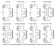
In Glass Audio 3/99 Menno showed 8 variation of PP schematic
That reference rang a bell. I was a subscriber to Glass Audio for most of the years it was printed. I no longer have my paper magazines since I had to move of Florida in a big hurry and gave away or trashed everything I did not want to move 1200 miles.
I don't have the copy of Menno and his transformers, but there was another interesting article in that same magazine.....the LW6-180 Amplifier. Let's see, 90 watts per channel, 10 Hz to 50 KHz frequency response, 0.16% THD using technology "in common with" that in the McIntosh MC275......unfortunately the builder made his own transformers and only minimal details about them are given.....the 6LW6 is however my favorite tube for building big amps.
Trust me, I've got both of Menno's books. The 1070-UC is the bifilar-wound transformer with two identical primary windings, one meant for anode, the other for cathode. He describes that transformer *always* in the context of the Unity-Coupled circuit. All circuit diagrams show those windings used as cathode windings.
The only thing that makes any possible sense is that the datasheet is mis-lableled. Either the part number on the front, or the windings in the figure.
The only thing that makes any possible sense is that the datasheet is mis-lableled. Either the part number on the front, or the windings in the figure.
I had the first of Menno's books, but I haven't seen it since I lived in Florida. For all of the years he was hawking those transformers there were two suppliers, Amplimo in the Netherlands I believe, abd Plitron in Canada.
Plitron was bought out several years ago and their line of audio toroids has vanished. Amplimo still has pull down menus for high end audio transformers and pro audio transformers, but they lead to blank pages.
The transformer linked to previously is on a web site with Vanderveen's name all over it, but no indication of who actually makes the transformers. There are other transformers on that site with cathode and screen windings in power levels up to 100 watts. No mention of "unity coupling" though.
I'm really happy with my Plitron transformers.
Me too. All of mine have Menno's name on them, so maybe he owns the rights to the designs and no longer licenses it to Amplimo or Plitron.
Tubelab George and Scott17, not often I get to see two great designers of amplifiers in the same thread. You guys (and a number of other long time contributors in this thread) have all my respect for the information, assistance, expertise, and knowledge you share without any expectation of gratitude. So thank you for posting in these threads. Some of it is old hat and repeated from over the years, but trust me when I say that I still read it all. I have learned more from not only following your designs, but making the amplifiers. The knoweldge of this hobby you share has given me a passion for this... and definitely kept me alive and safe.
I keep looking at my back issues of AudioExpress and Glass Audio with the very esoteric builds and numbers that impress me. After building your designs, I understand so much more and can recognize something with a LTP or is a parafeed design or output is UL or triode. I can talk about why certain vintage tube amps are the way they are. Tempted many times to build some of those Glass Audio designs, but I circle back to your designs. Both of you and your respective amplifier designs (George's Simple SE and Scott's Parallel SE) are simple and elegant and you guys have provided hours of audiophile level enjoyment to me and my friends.
As a heads up, I am now slowly building the EL34 Baby Huey as I try out a more powerful PP topology... this is right after I get my mini-room-heater-A, another pair of MoFos, and Aleph J completed (best sound as far as sand goes). And some repairs I have to do on some vintage silver face receivers from people who have been referred to me by friends (recapping and lightbulbs doesn't pay the bills but keeps these things from the landfill).
Anyway, thank you for contributing to this thread. I unfortunately ran out of things to say a while back.
I envy you in that regard. Wanted to work in either electronic product rsearch or development after obtaining my EE from U of A in Tucson. But fate carried me to ~ 30 years in prepress product support in printing business. Met and have to deal with quite a few true Royal bloods and wannabees along the way. It had been a lot of fun but also increasingly getting tighter last 5 years. Only a small and shrinking customer base commission prints to commercial print houses now, magazines and newspapers are going out of printing fast, they have no choice but to take the internet route. So I retire voluntarily end of 2017 and depend my income on a small homestyle finger food business at home, mostly for deliveries.I spent 41 years working for a big corporation, 30 of those were as an engineer in product development or research. Royalty is usually obvious and often avoidable....
")
I had been trained 100% in SS but discovered the magic of Direct Heating Tubes, DIYAudio, LTSpice and other mountains of information available through the internet after 2009. Just my luck, I can now get information as easily on brand new parts and obscure tubes made in 1920 in limited quantity. I am still overwhelmed after a decade.
I don't have any of Menno's books. On Veen2EN.pdf the 8 circuits are shown with same nothing for Unity Coupled Circuit 4. There are 4 other circuits using windings as cathode feedback but Menno does not name them Unity Coupled. Please confirm. I suspect Menno found something with Circuit 4 but would not mention anything, perhaps out of his respect to MacIntosh.... He describes that transformer *always* in the context of the Unity-Coupled circuit. All circuit diagrams show those windings used as cathode windings...
Datashets show 3.5% cathode feedback winding for the 1070-UC. On a non potted one, it is possible to manually add winding to allow Unity Coupled operation at feedback ratio 1.
Attachments
The datasheet is rather confusing giving labels of screen grid to a couple of windings and no reference to how they are to be used in circuits. Seems I mistook the single 3.5% feedback winding for cathode feedback use.Trust me, I've got both of Menno's books. The 1070-UC is the bifilar-wound transformer with two identical primary windings, one meant for anode, the other for cathode....
Last edited:
Hi, it seems that Menno van der Veen these days distributes his transformers by himself.
Welcome to Ir. Bureau Vanderveen
The transfomer VDV-4070 is perhaps a variant of the 1070 discussed previously, Specialist: VDV-4070-CFB-PPS?? On the bottom of the page there is a link to an article detailing the description of an amplifier using this OPT. Or is Cathode feedback an entirely different thing?
I hope not to annoy anbody with my limited knowledge, but before embarking on a build of a PP-amplifier i hope to get a good understanding of relevant concepts.
Please keep up the good discussions, Harry
Last edited:
Or is Cathode feedback an entirely different thing?
Cathode feedback is a similar concept, but a much broader descriptive term.
Cathode FeedBack(CFB) is a term that describes a circuit whereby feedback from a winding on the OPT is applied to the cathode(s) of the output tube(s). It can be a separate winding expressly for this purpose as found in some old Arcosound transformers, or it can be the speaker winding itself.
Cathode feedback attempts to correct some of the distortion caused in the output tube and the OPT by applying feedback to the output tube only, not over the entire amplifier as in Global Negative Feedback. The feedback ratio in this case is a small fraction of the plate voltage swing, usually less that 10%. A modest increase in drive signal to the output tubes is needed to offset the gain reduction caused by this feedback.
In a single ended amplifier (CFB) can make some cheap OPT's sound bigger than they really are and improve their bass response. If the OPT has design issues (unintentional, or intended for cost reasons) the cathode feedback may not offer an improvement, but rarely causes serious problems unless it is inadvertently applied with the wrong phase.
My SSE amp design can use CFB from the speaker winding as an option. I find that it helps the bass a lot when running a big tube like a KT88 in UL mode driving big speakers (15 inch OB drivers) with loud dynamic music like Pink Floyd. I prefer triode mode with no feedback at all with an EL34 or KT88 for less extreme music.
In a push pull amplifier cathode feedback can be used for the same reasons. In order for it to make an improvement, the OPT must be wound such that both halves of the primary and secondary are symmetrical. Phase and amplitude imbalances between the two halves can apply different levels of feedback to the different sides of a push pull amp. These imbalances will vary with frequency and can make matters worse at the low and high frequency ends of the audio range than no feedback at all. This has been the case with ALL of the cheap EI core OPT's that I have tested in a push pull amp. In some cases CFB provoked amplifier instability.
Some popular old tube amps employed CFB with good success. Audio Research was one of the popular companies to do this using the speaker winding. The OPT must be designed for this use though.
Unity Coupling is an extreme case of CFB. The feedback ratio is exactly ONE, and must remain one over the entire audio range in both amplitude and phase. The plate and cathode windings are essentially the same, and are often wound together (bifilar). This places extreme insulation requirements on the wire used in the OPT.
Unity Coupling reduces the voltage gain in the output tubes to two or less, requiring a LOT of drive voltage. Mac employed a positive feedback "bootstrapping" arrangement to get the voltage swing required to do this, but other methods exist, including the use of driver transformers.
The advantage to Unity Coupling is the removal of the distortion artifacts that occur as the output tubes pass through the "crossover" region where one tube shuts off and the other takes over.
The balance between the two halves becomes critical with a unity coupled OPT. Serious imbalance in the transformer can make the amplifier unstable with no hope of correcting it short of making a new transformer.
I bought a large quantity of cheap ($16 each) OPT's many years ago to make guitar amps. I have used them successfully in HiFi amps when driven by a low impedance circuit. They do NOT work well with CFB in any case. I have been meaning to try the Crowhurst twin coupled design with them, but haven done so yet.....someday.
On a non potted one, it is possible to manually add winding to allow Unity Coupled operation at feedback ratio 1.
I have managed to add CFB windings to "dumpster toroids" with limited success. I doubt that you could stuff enough wire through the hole, and get it even enough to work properly for Unity Coupling.
I envy you in that regard. Wanted to work in either electronic product rsearch or development after obtaining my EE
I got lucky in that regard. I walked into a Motorola plant in 1972 and got a job on the line tuning radios. I got out of that into a job keeping the factory running and maintaining test equipment. That lasted 10 years and was a HUGE learning opportunity.
I could see the decline in manufacturing beginning to happen in the 80's so I got a job in product development engineering. It took me a few years to become an "engineer," THEN they sent me to college to get a degree in engineering on THEIR dime......then they sent me for a Masters degree, again on their money. Neither were "top 20" schools, since I had to live within driving distance and work full time while going to school.
I left the product development group when I saw the end coming to Motorola's cell phone group (now owned by Lenovo). I worked in the research group for about 12 years until I got the invitation I couldn't refuse from the CEO...."you are part of a target group.....we will pay you to leave".....
Last edited:
... In a push pull amplifier cathode feedback can be used for the same reasons. In order for it to make an improvement, the OPT must be wound such that both halves of the primary and secondary are symmetrical. ....
Here is an unusual, maybe eccentric, push pull amplifier with a ton of cathode feedback, using a conventional output transformer, taken from the November 1955 issue of Radio Television News, available at the American Radio History website.
The whole issue is good, and worth taking a look at it, including an article by Crowhurst on load lines. Best I recall, his original article on Twin Coupling is in one of the Radio Television News issues from about this time. Once in a while twin coupled transformer sets appear as NOS on ebay, but out of my price range.
Attachments
Interesting article, and something I had never seen before. There are two scary statements in the text that would keep me from playing with this design though.
The output transformer is a Triad S-35A.......The entire circuit is designed around this transformer........translation, be prepared to tinker a LOT to make it work with a modern transformer having quite different characteristics.
a novel combination of features, namely 100% negative feedback around the output transformer, output and driver stages, together with sufficient POSITIVE feedback around the driver stage to CAUSE it to OSCILLATE in the absence of negative feedback.....A neon bulb shunting the grids of the output tubes limits the input voltage and prevents the destruction of the tubes in the event the speaker leads are accidentally shorted together. Shorting the speaker leads effectively removes the negative feedback and permits the drivers to oscillate........Translation, there is some load somewhere that will make this thing unstable and possibly oscillate. The speakers and transformers of today are quite a bit different than those produced in 1955. Magnets are stronger and the inductive kick back that a moving coil can produce can make the speaker's effective impedance look like a very low value when a kick drum hit tries to instantly reverse the woofer's cone travel.
Again, stability is not guaranteed, in fact building this with a random collection of junk box parts practically guarantees instability. Right above the parts list are the words "Parts should not be substituted in construction."
An amplifier of the type described here will not make a $5 speaker in a cardboard box perform like a $200 folded horn. It will try, and sometimes the effort becomes so strenuous that oscillation occurs. Such oscillations have been toughed off by overloading the amplifier during efforts to obtain resounding bass from tiny speaker enclosures.......
I tend to AVOID intentional positive feedback in an amplifier. Not the case in my vacuum tube music synthesizer. Neat idea though.
Last edited:
Some popular old tube amps employed CFB with good success. Audio Research was one of the popular companies to do this using the speaker winding.
exactly this final cathodes' NFB arrangement could be seen in some Audio Research amplifiers.
The schematic of their BIG BOY 150 watt per channel can be found in post #46 of this thread.
D150 monster amp and funny tooobz
Again, this doesn't work well with cheap OPT's.
The Boegli amplifier is an interesting design. It is using the secondary for CFB (N Fdbk) to the driver stage, instead of the usual CFB for the output tubes. Then it adds in POSITIVE Fdbks in the driver stage via the crossed R13 and R14, so as to make the driver gain very large. And THEN it uses triode configured output tubes besides.
Well, the secondary had better be WELL balanced symmetry wise for that design. With the high resulting gain in the driver stage, it really is just global N Fdbk, made to look like CFB. Phase shift in the OT from the load current will limit stability just like a typical global N Fdbk loop.
------------------------------
By the way, the Unity Coupled scheme does not fix the usual crossover distortion from tube gm variation. Seems to be a common mis-perception about UC. The AUDIO MAC designs still have to use class AB biasing to keep gm crossover dist. low.
The UC scheme prevents inductive spike distortion in class B when one winding is effectively disconnected by tube cutoff. Without the other tube conducting (class B) there is no low impedance on the other plate winding to transfer the inductive current too, as the magnetic field collapses, the winding voltage flybacks. Class AB conduction overlap prevents that in typical audio amplifier designs by keeping at least one tube always conducting, besides smoothing out the gm variation too. (the cross coupling caps in the Twin Coupled design perform the same function as UC for class B inductive spikes)
Last edited:
For a friendlier (less drive signal) version of UC (50% CFB), or of the Twin Coupled design (50% CFB), or Circlotron (50% CFB), one can take the Twin Coupled design and move the two cathodes inward on the bottom xfmr to the UL taps. This transforms a typical 40% UL xfmr set into a 28.5% CFB design. (0.4 / (1 + 0.4) ) Easier to drive. I've called this the Elliptron configuration (somewhere around year 2002), due to the asymmetry between plate windings and cathode windings. Cross coupled caps are used between identical taps on the two OT primaries, just like for Twin Coupled.
It also makes for a net resultant P-P OT that has the SAME primary Z as each of the original OTs. (using 16 Ohm secondaries in parallel to make the 8 Ohm output, same config. as Twin Coupled) Versus TWICE the original OT primary Z for the Twin Coupled configuration. This means that readily available off the shelf OTs will work straight away for Elliptron configuration.
You want a 3300 Ohm primary.... then just order two 3300 Ohm primary OTs, each of 1/2 power rating for a full power result. (actually will be slightly uprated from that, due to better use of primary copper)
Hence my earlier comments in the thread about winding UC xfmrs being a waste of time.
Either wind an easy high performance Circlotron xfmr, but deal with 50% CFB and dual power supplies,
or order Standard OTs and build an Elliptron with easy 28.5% CFB and a single conventional B+ supply.
Of course, the Twin Coupled design or the Elliptron could be custom wound on a single Long E lamination set (dual bobbins) to achieve higher BW performance.
Last edited:
I don't have any of Menno's books. On Veen2EN.pdf the 8 circuits are shown with same nothing for Unity Coupled Circuit 4. There are 4 other circuits using windings as cathode feedback but Menno does not name them Unity Coupled. Please confirm. I suspect Menno found something with Circuit 4 but would not mention anything, perhaps out of his respect to MacIntosh.
Datashets show 3.5% cathode feedback winding for the 1070-UC. On a non potted one, it is possible to manually add winding to allow Unity Coupled operation at feedback ratio 1.
The bottom row of figures are using transformers in the 10-20% CFB range (I can't remember right now how much his transformers have). The UC case in the upper right corner is the 50% CFB bifilar transformer (1070-UC). He notes in his book (and it is intuitively obvious) that the cross-coupled screen-to-plate connection in the UC circuit will not work with a normal CFB transformer of less than 50% CFB because there will be a whole bunch of positive feedback to the screen which will cause instability. In the 50% CFB case it works really well because the voltage between screen and cathode of each tube stays constant and the tubes operate as pentodes.
He mentions plenty about McIntosh and the circuit in his books and on his website where the transformer is for sale, so I don't think he is averse to sharing his thoughts on the circuit. The virtues of the circuit and large driving voltage required are well known.
Hi, it seems that Menno van der Veen these days distributes his transformers by himself.
Welcome to Ir. Bureau Vanderveen
The transfomer VDV-4070 is perhaps a variant of the 1070 discussed previously, Specialist: VDV-4070-CFB-PPS?? On the bottom of the page there is a link to an article detailing the description of an amplifier using this OPT. Or is Cathode feedback an entirely different thing?
I hope not to annoy anbody with my limited knowledge, but before embarking on a build of a PP-amplifier i hope to get a good understanding of relevant concepts.
Please keep up the good discussions, Harry
The VDV-4070 is not the same as the 1070-UC. That one is here: Specialist: VDV-1070-UC-PPS
- Status
- This old topic is closed. If you want to reopen this topic, contact a moderator using the "Report Post" button.
- Home
- Amplifiers
- Tubes / Valves
- DIY McIntosh Amp