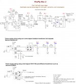
For those who may not be familiar with the Firefly here is the original circuit by none other then Doug Hammond himself. Not meant as a regular amp but for guitar effects. Notice the self inverting final stage, makes lots of even order harmonics, 2nd, 4th, 6th & so on.")
The 12AU7 Hammond uses in his circuit is not far off the characteristics of the 6SN7.
Beginning in the late 30s there were several of these self inverting PP stages built into various amplifiers for one reason or another. None of them are able to deliver more than one half what the same PP pair could do with a regular drive stage.
I did an exhaustive series of tests a couple of years ago, complete with distortion tests with an HP334A THD Analyzer & Pico Technology Spec A. The results were not good at all. Anyone wants a copy of the paper let me know, all in a PDF.
Attachments
Also, with the firefly rated at 1.5w I'd wonder about saturation. Maybe not a problem but...
With your analysis, are you saying not good for the intended purpose (effects pedal) or for audio purposes?Beginning in the late 30s there were several of these self inverting PP stages built into various amplifiers for one reason or another. None of them are able to deliver more than one half what the same PP pair could do with a regular drive stage.
I did an exhaustive series of tests a couple of years ago, complete with distortion tests with an HP334A THD Analyzer & Pico Technology Spec A. The results were not good at all. Anyone wants a copy of the paper let me know, all in a PDF.
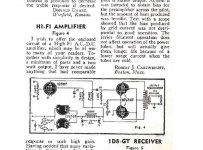
The cct is very good for effects. But makes a poor audio amp. In spite of that there are examples over many years of it being used for claimed Hifi, even recently. And found one in WW2, a couple more published in the late 50s & early 60s.
All covered in the paper. The example here is out of WW2. Could have made a real amp simply by stuffing in a 12SC7 diff amp, a real phase invertor instead of that 12SH7 pentode.
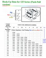
The Hammond 125A would be AOK in a small PP amp. Looking at the taps selected in the Firefly, could easily go to a higher load impedance, thus improving for fidelity.
In spite of that there are examples over many years of it being used for claimed Hifi, even recently. And found one in WW2, a couple more published in the late 50s & early 60s.All covered in the paper. The example here is out of WW2. Could have made a real amp simply by stuffing in a 12SC7 diff amp, a real phase invertor instead of that 12SH7 pentode.
The Hammond 125A would be AOK in a small PP amp.
Looking at the taps selected in the Firefly, could easily go to a higher load impedance, thus improving for fidelity.Attachments
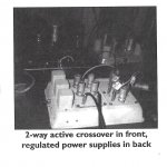
The Betty Crocker Special
Use of a cake tin as a chassis was inspired by an article in Sound Practices magazine, Issue 11.
Al Bryant was named ‘Home brewer of the Month’. One of the article photos shows a cake tin complete with electronics of some kind. Much lower cost than the purpose built thing & works very well.
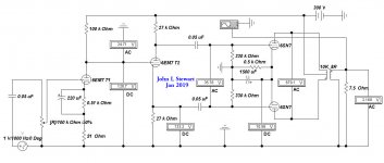
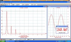
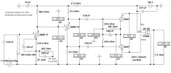
This amplifier is a PP 6SN7 driving into a Hammond 125E. Taps 1-3 connected to 7.5R result in a plate to plate load of 27K. Trying other close tap ratios confirm this to be the best option. The maximum audio looks like One Watt at which point the cct is clipping. The distortion is 4.3%. At 0.5 Watt the distortion is 2.2%.
The power supply is a regulated lab supply set to 300V. The driver circuit uses a dissimilar triode, the 6EA7. The high mu section is used in the first stage for gain. The other triode is low mu & makes a very good driver for the PP 6SN7 triodes.
When using twin triodes such as 6SL7 or 6SN7 the driver cct is never optimized for one part of the cct or the other. Using a dissimilar triode solves this problem. The 7247 was developed to overcome the problem but never caught on. One section is high mu like half of a 12AX7 while the other side looks like one half of a 12AU7.
Use of a cake tin as a chassis was inspired by an article in Sound Practices magazine, Issue 11.
Al Bryant was named ‘Home brewer of the Month’. One of the article photos shows a cake tin complete with electronics of some kind. Much lower cost than the purpose built thing & works very well.
This amplifier is a PP 6SN7 driving into a Hammond 125E. Taps 1-3 connected to 7.5R result in a plate to plate load of 27K. Trying other close tap ratios confirm this to be the best option. The maximum audio looks like One Watt at which point the cct is clipping. The distortion is 4.3%. At 0.5 Watt the distortion is 2.2%.
The power supply is a regulated lab supply set to 300V. The driver circuit uses a dissimilar triode, the 6EA7. The high mu section is used in the first stage for gain. The other triode is low mu & makes a very good driver for the PP 6SN7 triodes.
When using twin triodes such as 6SL7 or 6SN7 the driver cct is never optimized for one part of the cct or the other. Using a dissimilar triode solves this problem. The 7247 was developed to overcome the problem but never caught on. One section is high mu like half of a 12AX7 while the other side looks like one half of a 12AU7.
Attachments
Neat
I love old school builds like that. I wonder how it will sim with a bit of feedback to the driver cathode, I'm not too familiar with the 6EA7, 6EM7 or 7247.
Ideally, one could use a separate driver tube and splitter tube, but then the layout doesn't look symmetrical anymore
I love old school builds like that. I wonder how it will sim with a bit of feedback to the driver cathode, I'm not too familiar with the 6EA7, 6EM7 or 7247.
Ideally, one could use a separate driver tube and splitter tube, but then the layout doesn't look symmetrical anymore

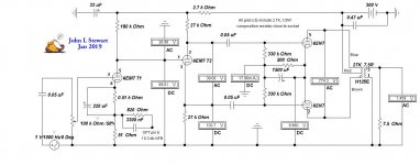
Corrected schematic here this time.
Hammond 125E with some impedance data extended.
Dissimilar twin triodes 7247 & 6EA7 (same as 6EM7).
Hammond 125E with some impedance data extended.
Dissimilar twin triodes 7247 & 6EA7 (same as 6EM7).
Attachments
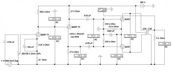
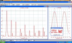
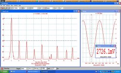
Another Episode of the 6SN7 amp, this time with NFB. A lot of work for one watt of audio but could be easily scaled up. The NFB is 10.3 db thru an 820R resistor from pin 6 of the Hammond OPT. The correct connexions are on the schematic. The 3300 nF cap in parallel corrects overshoot on a square wave.
3db down freqs are now 26 Hz & 63 KHz.
3db down freqs are now 26 Hz & 63 KHz.
Attachments
Looks like a low impedance node so not too unusual, if you used an unbypassed cathode resistor and made everything an order of magnitude higher resistance the capacitance would scale smaller too.
Edit- at first I thought thought it read as 3300 picofarads, so yeah, it does seem a bit high...
Edit- at first I thought thought it read as 3300 picofarads, so yeah, it does seem a bit high...
Last edited:
Looking back at some old notes that I found, when I did the big five channel 6AS7G/6N13S build years ago, I was using a red LED cathode load (in lieu of a bypassed cathode resistor) on 6SL7/6N9S gain/concertina drivers, with 50VA Antek toroids as outputs. I settled on 1500pF~2200pF across a 1K feedback/47R cathode resistor, I forget which of the two for sure. I do know that it took a few experiments to determine which gave the sharpest square with barely perceptible to almost nonexistent overshoot.
Interestingly, no feedback compensation was needed (just ever so slight rounding on leading edge was present) with 6SN7 driver/splitters, but the gain was insufficient for general use without a preamplifier, even with bypassed cathodes and CCS plate loads.
Interestingly, no feedback compensation was needed (just ever so slight rounding on leading edge was present) with 6SN7 driver/splitters, but the gain was insufficient for general use without a preamplifier, even with bypassed cathodes and CCS plate loads.
Just noticed again there was still another error in the schematic, I had mislabeled the OPT again. So finally fixed.
I've been looking at 6BL7s & 6BX7s for the output stage, using the same sim as before. Just need to change a few things such as the OPT ratio & biasing to get quick answers. Sometimes the dregs follow the cct & show up where I don't want them.
The max output of any amp is determined by the max plate watts dissipation. Both 6BL7 & 6BX7 can dissipate about 2/3rds more than 6SN7. So more audio is possible. All could be pushed somewhat more by biasing toward Class AB. With some increases in distortion. Something to try.
Attachments
Could be done. But results in crossover distortion as the signal is passed from one side to the other of the PP amp. It was common in the 1930s when higher power for public address systems was required. Beam power tubes like the 6L6 family solved that problem. Was also used in modulators for transmitters.
The tubes used were most often high mu triodes. That way they could be used at zero or very little bias.
The distortion is worse at low levels. In an audio system for critical listening Class B is probably not a good solution.
The tubes used were most often high mu triodes. That way they could be used at zero or very little bias.
The distortion is worse at low levels. In an audio system for critical listening Class B is probably not a good solution.
- Home
- Amplifiers
- Tubes / Valves
- 6SN7 push pull flea amplifier project