I've done it with a 6P45S amp I built (triode connected, naturally). I had it set to 12ma instead of 120ma and it sounded fine.
I get the sense that most folks on DIY have not much more than a VOM meter of some kind. A few with a lot more. Trying to come up with something of value is difficult without the tools.
Test equipment of quality has never been cheaper than today. Yet few have much, even tho they may have spent serious $$$$ on questionable boutique parts, resisters, caps & so on. They won't help much unless the differences can be measured with more than ones ears. Subjective tests are simple at best, simply some ones opinion. Others may differ & often do.🙂
Using the test mule & subing various cathode resisters for the 6SN7, I measured the following-
With the normal 500R Cathode Resister, Bias is 9.41V
At 0.5 Watts out Distortion is 1.86%, mostly 2nd H
At One Watt out Distortion is 3.31%, mostly 2nd H
With the cathode resistor increased to One K, Bias is 10.93V
At 0.5 Watts out Distortion is 2.65%, mostly 2nd H
At One Watt out Distortion is 4.6%, mostly 5th H
With the cathode resistor increased to 2K, Bias is 12.14V
At 0.5 Watts out Distortion is 7.47%, mostly 3rd H & many others
Test terminated, refer to the spectrum.
If you like harmonics, this is the setting for you.😀
Attachments
-
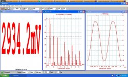 PP 6SN7GTB Amp One Watt 0.5 K Cathode Resister 9.41V Bias.JPG182.2 KB · Views: 332
 -
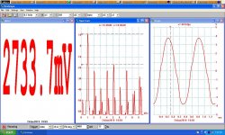 PP 6SN7GTB Amp One Watt One K Cathode Resister 10.93V Bias.JPG181.6 KB · Views: 321
 -
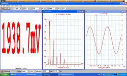 PP 6SN7GTB Amp 0.5 Watt One K cathode resistor 10.93V Bias.JPG178.1 KB · Views: 310
 -
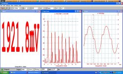 PP 6SN7GTB Amp 0.5 Watt 2K cathode resistor 12.15V Bias.JPG184.5 KB · Views: 308
Pls post a copy of the schematic. THX🙂I've done it with a 6P45S amp I built (triode connected, naturally). I had it set to 12ma instead of 120ma and it sounded fine.
Yes. It's fixed bias. 1.2V across 10R = 120ma. Cathode biased 6P45S requires ~60V drop @300V B+ (roughtly a 500R 10W resistor).
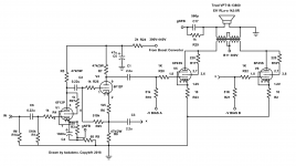
The PP 6P45S Amp looks pretty straight forward. But I have a couple of concerns as follows-
1) the 6P45S & its equivalents were designed for operation as horizontal sweep tubes. In that application the cct designer always provided a degree of protection somewhere in the cct to prevent max current from flowing should the bias fail during operation. There is nothing like that in this cct.
A fuse in the HT lead may be a way out. But should be under the chassis to force turn off of the HT for safety while replacing.🙂
2) After some digging, it turns out the triode mu of the 6P45S is three. Finally found that on a Russian data sheet, odd that the number does not appear on other data sheets. Mu of three is getting into a region where fixed bias is dangerous, thermal runaway is a possibility. I've seen it with the 6AS7/6080 family, mu of 2. The tube expires very quickly. People trying to build OTLs spend considerable time matching tubes for that kind of operation, cathode bias can't be used. In that service life is very limited.
During my days in research I've used a similar tube, the 6DQ5. But as a pulse generator. I found it is possible to stuff a 1.5 Ampere pulse into a 50R transmission line. Just what was needed for some R&D on magnetic cores for computer memory.🙂
2) The driver triode is on the anemic list sofar as low distortion to the output grids are concerned. A good design attempts to make the following grid resister as large as possible in relation to the resistor that is driving it. So for the subject amplifier looks like barely greater than One (51/47). That is a source of considerable distortion. In a SE amp it appears as even order (2nd, 4th..... Etc) distortion. In a PP amp it causes odd order (3rd, 5th... Etc) distortion. The solution is a better driver triode, would be something like what is found in a vertical amplifier tube. That is what I did for the PP 6SN7 amp.
In that case the ratio is >12:1.😀
Your amp biased a long way toward cutoff & with the inadequate driver will show quite a bit of distortion on the test bench. But some folks like that.
Rock guitarists have all this built into their amp head. But these days it is normally done at low level, switched in or out by the performer. The main amp driving the speakers is very linear.
Don't need to know much to be an engineer, just where to look it up!!🙂🙂
Attachments
1: The 10R resistors are 2W and will open (burn out) in the event of a thermal runaway.
2: It's biased at 35W per tube. That's hardly toward cutoff. In the schematic above, the class A power is over 10W. We were just talking about the idea of using 1/10th the bias current as a trade off between distortion and Pd.
The 6F12P is hardly a wimpy triode. 19.5 mA/V, mu=100. As far as those ratios, I've never heard about it or how it would effect sound (EDIT: Yes I do, Zout vs Zin, right?). I've picked 51k to limit the possibility of thermal runaway. I'm also using an autobiasing circuit that will try to reign in any current excursions. There is also about 8db feedback which serves to make a nice square wave at 10 kHz.
If you have a schematic that you think should replace the 6F12P section, please share it. If not, one could just parallel 2 6F12P tubes, no?
Koda
Last edited:
1) for 2W in the 10R resister it will take 0.2A. It will simply get hot, won't blow at that. Depending on the ambient temp inside the chassis could need quite a bit more current.
2) the 6F12P has a nice G spec, both sections. What it will need to drive lower R's in the phase splitter is better Pd. So still wimpy when it comes to doing the work it needs to do. 51K in the grid ccts is a good move. But not a sure thing.
Attached is a cct that uses two triodes for part of the phase splitter. For your app the plate resisters driving the output stage need to be reduced to something like 12K each. Double triodes with enough Pd would be something like 6BL7 or 6BX7 (12W total per tube). To get enough gain two stages are in the drive cct.
This cct works well, I've used it several times in experimental amps going back about 20yrs. The biasing arrangement for the output tubes is also good. See my article on it.🙂
Just hit the wrong button!!😀Here is the article on biasing from 2002.🙂
Attachments
Thanks for the attachments. As far as the 2W resistor 200ma is fine, the tube will peak 700ma in operation. If it runs away it will try and flow over 1 ampere continuous, destroying the resistor (ask me how I know LOL). Ambient chassis temp is about 70c.
Swinging 60V across 51k is only 1.1ma. 70mW. I still don't see why this triode can't deliver that low power, especially since it seems to work fine. It's rated for 3.5W Pd which is the same as a 6CG7 that a lot of designs use. Yes, I'm not including Cmiller. As far as biasing, I'm using these for it. Module AB-4 for 4 tubes, PP & PPP amps, requires 6.3VAC & bias supply from the amps circuit, with TTL error signal output. TES
Swinging 60V across 51k is only 1.1ma. 70mW. I still don't see why this triode can't deliver that low power, especially since it seems to work fine. It's rated for 3.5W Pd which is the same as a 6CG7 that a lot of designs use. Yes, I'm not including Cmiller. As far as biasing, I'm using these for it. Module AB-4 for 4 tubes, PP & PPP amps, requires 6.3VAC & bias supply from the amps circuit, with TTL error signal output. TES
Last edited:
AC vs DC Loadlines
The example I picked is typical of any RC coupled amplifier, due to curvature of the tubes characteristics as the grid is driven more negative. Pentodes have the same problem.
The grid bias curves of equal voltage spread out as the grid is driven more +ve. And more -ve, the lines tend to bunch up. Paralleling the following cct results in further deterioration. The peak to peak output capability is compromised.
I was not able to find any data on the 6P45S running at 300v on the screen. Need that to determine the grid volts for proper operation. Its not indicated on your schematic.
For a mu of 3 I'm thinking the grid bias is something like -60V. In which case each grid would need 120V peak to peak for full drive. If a single tube is used that would be a total of 240V peak to peak. Even order distortion in the driver is a sure thing. Picking a lower plate load resister &/or a higher following grid resister would help.
And keep in mind the designers of both the tubes used were not considering the needs of audio amplifiers. Both were designed for specific needs, so might be OK & perhaps not. Thinking about the cathode resisters failing, are they capable of starting a fire?😀 All things to think about when designing from the ground up!!🙂
Attachments
Class B
I have built a several class B amps Using 811A /572b that run at 600volts. for 100watts output
The current draw is 70ma per tube according to the Makers the { used as record cutting amps}have 40 watts class A..{ A Friend worked it out as 27 watts class A}. The 572B plates can handle over 100 watts, the 811a 65 max. The out put transformer is 2 k P-Plate..
The 6bl7/6BX7 Only have 12 watts, so you can't use much current if you run them class B.
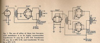
All very nice but not exactly a flea amplifier project. Probably should be in its own thread. NTL, all Class B, will still have cross over distortion, percent increases at low levels. Not good for HIFI. But OK in a Public Address system or AM Modulator.
Attached are a couple of 12AX7 amps running as Zero Bias triodes in Class B. Perhaps they could qualify as a flea project. But looking at the plate volts & current the tubes may have a short life!!🙂
Attached are a couple of 12AX7 amps running as Zero Bias triodes in Class B. Perhaps they could qualify as a flea project. But looking at the plate volts & current the tubes may have a short life!!🙂
Attachments
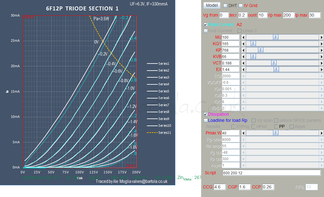
I wonder what those load lines would look like on an actual 6F12P... Too bad these curves only go to 200V
- Home
- Amplifiers
- Tubes / Valves
- 6SN7 push pull flea amplifier project