You could bias the 6AS7 sections by using bypassed TL783 as CCS instead of cathode resistors.
Thanks. I am planning on doing something like that, but I want to compare it with garter bias. I love the simplicity of the garter.
The 6AS7 is a heater monster, and cathode bias wastes a lot of heat. The tube isn't recommended for fixed bias. It's not an easy tube to work with sometimes. But it does look nice and glows just nice with exposed innards.
Yes, the power waste is a concern for me and I don't necessarily expect to keep what I come up with. My work on this is primarily about learning, not so much to design the best amp.
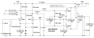
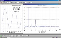
Here are the results for the PP 6BX7 vers of this amp. Still using the Hammond 125E OPT it clips at about 3 watts on a 250V PS. OK for a small amp. At no signal the total plate dissipation is 11.5 Watts. The 6BX7 cathodes are separately biased. For out of spec tube sections of +/- 10% this hookup reduces the unbalance plate current to 2%.
The driver is still the 6SL7 as used on the original. But not sure if Ling meant the two sections to be direct coupled or cap coupled. For the direct coupled version neither of the triodes operates in the best mode. So to get large output to the following grids AC coupling solves that problem. Since this amp is not meant for NFB, cap coupling is not a concern.
Seems odd but looking at the distortion at clipping actually goes down a bit for 2H & 3H. But that is replaced bu a spectrum of higher order harmonics.😀
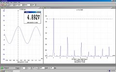
During work on the PP 5998 vers I tried the 6SL7 in a differential connexion with an NPN transister for the cathode tail. The gain was somewhat less, but the distortion was also about one half of this version. Gain shewn is from the 6SL7 grid to the 7.5R load.🙂
Just found this. I like it 🙂
Original intent is cap-coupled or a step network, so this is in the spirit of the design for sure 🙂
I have been toying with a CCS-tail differential on paper, but I'm getting a bit burnt out lately, so haven't tinkered much 🙁
I'll have to try out a differential version soon. Maybe I'll rewire the original prototype, it lives in the garage right now.
The 6AS7 is a heater monster, and cathode bias wastes a lot of heat. The tube isn't recommended for fixed bias. It's not an easy tube to work with sometimes. But it does look nice and glows just nice with exposed innards.
I really, really like the 6AS7, nice "showpiece" type of tube for simple amplifiers. Cheap. Standard pinout. However- It's inefficient, strange characteristics make it "tricky" to use, and it's power limited. Good option for a garage amplifier or seldom-use rig for some cool points. There are better options. A push pull EL86 or 6P43P-E triode would be a good design evolution.
The original cct did use garter bias. But I found that if separate cathode bias resisters were used that was sufficient to get good DC balance. OK for common EI stacked OPTs. Garter might be worth doing for a toroidal core OPT.
Keep the cct as simple as possible!
The PP 6BX7 works very well, make a good bookshelf amp. Three watts can make a lot of noise thru a good speaker in a small to medium size room.
This has been an interesting exercise, easy to get a lot of measurement data. So starting with the 6SN7, I tried the 6BL7 & 6BX7. Available audio is limited by plate dissipation. So for the 6SN7, audio is about One Watt max in Class A. For the 6BX7 6BL7 about 3W. But real clean. But very dependant on the drive cct.
A friend brought a 5998, something I'd never seen before. That one was a surprise, I had designed & built many regulated PS over the years both constant voltage & constant current. All the way up to a 4500V, One ampere brute. The 5998 manages 10 watts at clipping. The D% results are very good.
All of these looked great with no NFB. All running thru a Hammond 125E OPT. Should look better thru a Lundahl.
Attached some info on the PP 6BL7 vers. This one has an early variation of the Diff Amp front end.
More later.🙂
Attachments
Ping Lingwendl
Did you get your PCBs completed? The test results for both the 6SN7 & 6BX7 versions looked very promising.🙂
Did you get your PCBs completed? The test results for both the 6SN7 & 6BX7 versions looked very promising.🙂
Nope 🙁
I've been super busy and had some health issues, so other than some aquarium projects I've not had time for anything lately. I have a few opamps to review and then I'll try and revisit things again.
I've been super busy and had some health issues, so other than some aquarium projects I've not had time for anything lately. I have a few opamps to review and then I'll try and revisit things again.
jhstewart9,
In post #367 you talked about individual self bias resistors to get current balance in the output stage. I do that too, it works well.
But your schematic in the same post shows a common self bias resistor for the output tubes. It probably was not updated.
In post #367 you talked about individual self bias resistors to get current balance in the output stage. I do that too, it works well.
But your schematic in the same post shows a common self bias resistor for the output tubes. It probably was not updated.
You are correct, that is an earlier schematic. Best way to run these circuits is with separate cathode bias resisters. DC balance is very much improved for the OPT. The improvements measured are somewhere in an earlier post. Think I did it for the 5998 double power triode sample whose sides were not matched well.
But might still need AC balance to further improve the performance. Could we hear it? Maybe. But not me, at 86 my left ear is shot😀!!
Spring finally got here, so today on the tractor & moving loads of leaves to the huge pile on the back 40! Missed quite a bit last fall.
But might still need AC balance to further improve the performance. Could we hear it? Maybe. But not me, at 86 my left ear is shot😀!!
Spring finally got here, so today on the tractor & moving loads of leaves to the huge pile on the back 40! Missed quite a bit last fall.
jhstewart,
We will have to go to an Audio audition event together. My right ear is shot. One left and one right ear checks out stereo.
We will have to go to an Audio audition event together. My right ear is shot. One left and one right ear checks out stereo.
The subject amp just now cranked up again & measured the cathode currents in the output 5998 as follows-
Separate 750R cathode resisters, 52.6 & 50.9 mA, a ratio of 1.0334. With the cathode resister paralleled, 56.8 & 46.7 mA, a ratio of 1.2163. A very good improvement. Should be no problem with common EI core OPTs.
I like the separate Rk for the simplicity & reliability of the cct. But OTOH, I've built quite a few amps with a common Rk.😀 Don't use a common Rk with the 6AS7/6080 family. I tried that 20yrs ago & watched one expire quickly as current hogging took over. A hole was cooked in the grid structure of one of the triodes.😱
The 6sn7pp is a great amplifier!!
I built this similar design 8 years ago, and it performed great!
Gave it away as a present to family member. Prior to the 6sn7pp amplifier I assembled a 12au7pp amplifier and still have a demo on Y.T. back then I uploaded a few things to remember how they sounded. If you would like to hear what a smallish 12au7pp amp sounds like here it is.... 😎
YouTube
Just for interest and curiosity
livingdeliberately,
That was great. As always, a schematic would have been appreciated. But then, I have built many amps, and did not draw a schematic for some of them (me too).
That was great. As always, a schematic would have been appreciated. But then, I have built many amps, and did not draw a schematic for some of them (me too).
6A3sUMMER
It has been 8 years, and moved to different state. I couldn't find it, however I will build again and post as soon as I finish my kitchen. "Mid-point of new cabinetry.
It has been 8 years, and moved to different state. I couldn't find it, however I will build again and post as soon as I finish my kitchen. "Mid-point of new cabinetry.
6A3sUMMER
It has been 8 years, and moved to different state. I couldn't find it, however I will build again and post as soon as I finish my kitchen. "Mid-point of new cabinetry.
Sadly, Linwedil has a history of very interesting ideas but no follow-through.
I already posted on the other thread, so I think that reply sums it up pretty good, but I'm not sure how to take your comment, it's true but not really the nicest way to say it. I make no promises on anything, and share my ideas and projects as a fellow hobbyist, nothing more. I'm sorry if that doesn't work for you. I have other responsibilities and health issues to deal with that take priority.
Although I haven't mentioned previously, it's fairly hard to use a soldering iron with intermittent, unpredictable tremors in your hands that cause you to hurt yourself.
Although I haven't mentioned previously, it's fairly hard to use a soldering iron with intermittent, unpredictable tremors in your hands that cause you to hurt yourself.
Due to various reasons, I haven't been able to send out untested boards to those interested. I will bring a few with me to Burning Amp to give away, but for everyone else, I have attached the PCB gerber files here. These will allow you to order your own from various PCB suppliers, with my previous experience being very affordable and favorable with JLCPCB. For example, JLCPCB will do 5x PCBs for $14.86USD via economy shipping, or $24.91 via DHL int'l express.
Here is the EasyEDA link to the project, for those who want to check it out directly-
flea amplifier - EasyEDA
Both the octal input and noval input are 120mmX100mm. I have tested both and they function correctly, with no real issues.
I plan to do a revision eventually to try and bring the size down to 100mm square, implement a ground plane, and make several changes to a less universal, more "classic" style, with basic self biased concertina, regular individual cathode bias resistors on the output stage, and maybe even a differential splitter version. This will simplify the circuit and PCB considerably, and satisfy the purists as well. I'm planning a driver PCB that would be easy to rework into such a configuration, as it would basically be a concertina into a differential for use with offboard power tubes and sockets for larger projects. Just need to find the time, but with the holidays coming up I should be able to work something up.
I apologize for being so slow and inactive with progress. I'm going to make an effort to finish some projects soon so that I can release more PCBs and make revisions to existing projects. I have a handful of unfinished things that really need to get done.
Attachments
Last edited:
Ling,
Were you able to confirm that the PCB is working properly? That's what I thought the idea was for sending out the PCBs to a few testers. If a bunch of us produce boards and find errors, that'd be unfortunate. Maybe someone here could offer to produce them and distribute a few for testing (perhaps at a small cost)? I'm far too busy, haven't been at my bench in months, but cooler weather is arriving and I may be able to re-start soon.
Also, did you create a file for the 6AS7 version? Just curious...
Carl
I didn't have any errors on the batch of each made other than a cosmetic spot where a trace went past the pad a few mm, and I think a couple minor silkscreen labeling issues. I built one of each and fired them up, no issues that I could find, both functioned correctly and sounded great. I would greatly appreciate if a second set of eyes could pull up the link to the project and give them a look, however. The EasyEDA page is easy to use, but a Gerber viewer should work too. I mainly wanted others to confirm that it all looked good and worked really.
Sorry to hear about the poor health Lingwendil! I've enjoyed the learning to be had in this thread, and cheers for the idea. I'll build one eventually, with or without a pcb (I've sorted the parts as of a while ago). But as someone with a large number of planned projects I'm in no rush. 🙂
It seems pretty self evident to me that it's Do it *Yourself* Audio, not 'wait for someone to do it for you' audio...
It seems pretty self evident to me that it's Do it *Yourself* Audio, not 'wait for someone to do it for you' audio...
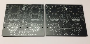
Thanks to Lingwendil for the good work he has done. I've just received 10 noval boards ordered to JLCPCB with the gerber file on post #375. I now clearly see the many hours of CAD design poured on this PCB; it is still rough on some parts but it looks a quality part overall.
I selected the black finish because the holes on the chassis for the noval tubes must be slightly larger than the tube sockets: noval sockets are shorter than the octal ones, and will be recessed in the chassis. The black board is less noticeable while peeking trough the hole, and the white silkscreen is easier to read while assembling.
There are minor silkscreen overlap cosmetic errors already mentioned by Lingwendil, but they dont harm the assembly in any way. I have a few suggestion already for future versions.
On this board, the silkscreen does repeat the same component number on both channels. There are two R1 parts (for the left and for the right channel), two R2 etc. It is more usual to have unique labels for each component. A popular choice is to add 100 to the part number: R1 on right and R101 on left; R2 and R102 etc.
Another suggestion: mark the pin 1 of octal sockets on both sides, or make the copper square. I will mark pin 1 on the back side of my board with a spot of white marker.
I will place terminal blocks on the side opposite of the sockets, and they will cover the very small silkscreen labels. Labels would have been better placed behind the terminal block perimeter, instead of inside it.
The Lingwendil email address on the back silkscreen is near to the mounting holes and will be partially covered by the mounting screws.
I will start the assembly soon (hopefully!) and will post again the results.
Attachments
Man, those look really slick in black!
Please do comment on anything you think should be revised like you've already done. I'll make sure to implement the suggestions as I can. These were my first PCB design, so there is plenty of room to improve on future revisions. The silkscreen for sure stands out to me as needing major improvement, and I would love to try and shrink the boards down to 100mm square to make them cheaper to order for hobbyists as well. I think the redesign will feature a ground plane and smaller capacitor footprints to try to tidy things up considerably.
Let me know how it goes! Feel free to post pics as you go on here to document things or any issues 🙂
- Home
- Amplifiers
- Tubes / Valves
- 6SN7 push pull flea amplifier project