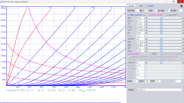
I have attached Model1_G2_600.jpg, which is your model but with S2 = 600 V; for comparison with your S2 = 500 V plot. Comparing it with the published S2 = 600 V data, it looks like model is still valid and accurate. Thanks very much for publishing this model.
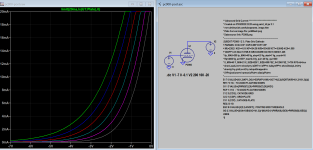
Updated GU-81 Spice model. GU81_LTSpice_051823.zip contains seven pentode-connection simulations corresponding to plots in the attached GU81.pdf. Please find the comments at the top of each schematic (.asc) file. There are also simulations for two sources of triode-connected data.
GU_81_Triode_1.plt:
https://www.diyaudio.com/community/attachments/gu-81-k-musatov-und-o-rasin-jpg.1117595/
GU_81_Triode_2.plt:
http://www.alexkurrasch.com/amp/data/gu81m-triode-connected-data.txt
For each of these nine cases, the LTSpice simulation plots are in reasonable agreement with the datasheets/measured data.
The GU_81_LTSpice.mod is based on the earlier one here: https://www.diyaudio.com/community/threads/vacuum-tube-spice-models.243950/page-163#post-6944473
Two things were changed. First, the plate and screen current plots corresponding to the transfer characteristic curve from page nine of the GU81.pdf had discontinuities corresponding to G1 = -10 and 0 V, please see the plot below (sorry about the poor contrast). That was found to be caused by the "LIMIT" function in the E22 calculation: E22 22 0 VALUE={V(21)LIMIT(KNK-V(G,K)*KNG,0,0.3)(-ATAN((V(P,K)-KNPL)/KNSL)+ATAN((V(P,K)-KNPR)/KNSR))}
I'm not sure what the purpose of the E22 calculation is, but setting it to 0 fixed the problem, and now this and other simulation plots agree well with the data. It is important to note that discontinuities such as this in the models gives Spice major problems with convergence to a solution, both with the DC (.op) solution and with transient (.tran) simulations.
The other change from the original .mod file was to modify parameters related specifically to G1 current with positive input voltages, which simulated about 25% compared with published data in the original .mod file: see pages 12 and 13 in the attached GU81.pdf.
Hopefully one can unzip the attached file, and everything will work out of the box with LTSpice installed. It may be necessary to add the unzipped path to the component symbol library.
Bill Schintler
Attachments
Hi all
I got 5 "Golden Samples" back (which are not mine), for the sake of measure those again, now under hot plate conditions.
Typically, there isn't too much of difference, but sometimes...
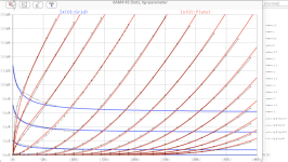
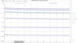
The first I measured was the 6AM4, and this tube showed significant curve changes when hot:
So, here the new i6 model.
BR Adrian
I got 5 "Golden Samples" back (which are not mine), for the sake of measure those again, now under hot plate conditions.
Typically, there isn't too much of difference, but sometimes...
The first I measured was the 6AM4, and this tube showed significant curve changes when hot:
- gm got about 25% larger
- mu got about 5% smaller
So, here the new i6 model.
BR Adrian
Code:
*6AM4 LTspice model based on the generic triode model from Adrian Immler, version i6
*A version log is at the end of this file
*100h BurnIn of 10 tubes, sample selection and measurements done in Dec 2021
*Params fitted to the measured values by Adrian Immler, May 2023
*The high fit quality is presented at adrianimmler.simplesite.com
*History's best of tube decribing art (plus some new ideas) is merged to this new approach.
*@ neg. Vg, Ia accuracy is similar to Koren models, and unrivaled for remote cutoff triodes
*@ small neg. Vg, the "Anlauf" current is considered.
*@ pos. Vg, Ig and Ia accuracy is on a unrivaled level (including neg. Va range!)
*This offers new simulation possibilities like grid resistor bias, backward plate modulated stages,
*Audion radio circuits, low voltage amps, guitar distortion stages or pulsed stages.
*            all 6AM4s seen share the same construction (so, no company letters needed)
*            |  anode (plate)
*            |  | grid
*            |  | | cathode
*            |  | | |
.subckt 6AM4.i6 A G K
+ params:
*Parameters for space charge current Is (100% assigned to Ia @ Vg < 0)
+ mu   = 143   ;Determines the voltage gain @ constant Ia
+ rad  = 9k2   ;Differential anode resistance, set @ Iad and Vg=0V
+ Vct  = 0.11  ;Offsets the Ia-traces on the Va axis. Electrode material's contact potential
+ kp   = 252   ;Mimics the island effect
+ xs   = 1.5   ;Determines the curve of the Ia traces. Typically between 1.2 and 1.8
+ kIsr = 220m  ;Va-indepedent part of the Is reduction when gridcurrent occurs
+ kvdg  = 65   ;Va-depedent part of the Is reduction when gridcurrent occurs
*
*Parameters for assigning the space charge current to Ia and Ig @ Vg > 0
+ kB   = 0.16  ;Describes how fast Ia drops to zero when Va approaches zero.
+ radl = 5     ;Differential resistance for the Ia emission limit @ very small Va and Vg > 0
+ tsh  = 20    ;Ia transmission sharpness from 1th to 2nd Ia area. Keep between 3 and 20. Start with 20.
+ xl   = 1.2   ;Exponent for the emission limit
*
*Parameters of the grid-cathode vacuum diode
+ kg = 175     ;Inverse scaling factor for the Va independent part of Ig (caution - interacts with xg!)
+ Vctg = -0.45 ;Offsets the log Ig-traces on the Vg axis. Electrode material's contact potential
+ xg   = 1.0   ;Determines the curve of the Ig slope versus (positive) Vg and Va >> 0
+ VT   = 0.132 ;Log(Ig) slope @ Vg<0. VT=k/q*Tk (cathodes absolute temp, typically 1150K)
+ rTr  = 0.65  ;ratio of VT for Igr. Typically 0.8
+ kVT  = 0     ;Va dependant koeff. of VT
+ gft1 = 0.05  ;reduces the steering voltage around Vg=-Vg0, for finetuning purposes
+ gft1a= 0.3   ;reduces the steering voltage around Vg=-Vg0. Effect decreases with 1/(1+kB*Va)
+ gft2 = 0.1   ;finetunes the Igr drop @ incrasing Va and around Vg=-Vg0
*
*Parameters for the caps
+ cag  = 2p4   ;From GE datasheet
+ cak  = 0p16  ;From GE datasheet
+ cgk  = 4p4   ;From GE datasheet
*
*special purpose parameters
+ os = 1       ;Overall scaling factor, if a user wishes to simulate manufacturing tolerances
+ murc = 10    ;Mu of the remote cutoff triode
+ ksrc = 10G   ;Inverse Iarc gain factor for the remote cuttoff triode
+ kprc = 1k    ;Mimics the island effect for the remote cotoff triode
+ Vbatt = 0    ;heater battery voltage for direct heated battery triodes
+ Vdrmax = 100 ;max voltage of internal Vg drop, for convergence improvements
*
*Calculated parameters
+ Iad = {100/rad} ;Ia where the anode a.c. resistance is set according to rad.
+ ks = {pow(mu/(rad*xs*Iad**(1-1/xs)),-xs)} ;Reduces the unwished xs influence to the Ia slope
+ ksnom = {pow(mu/(rad*1.5*Iad**(1-1/1.5)),-1.5)} ;Sub-equation for calculating Vg0
+ Vg0 = {Vct + (Iad*ks)**(1/xs) - (Iad*ksnom)**(2/3)} ;Reduces the xs influence to Vct.
+ kl = {pow(1/(radl*xl*Ild**(1-1/xl)),-xl)} ;Reduces the xl influence to the Ia slope @ small Va
+ Ild = {sqrt(radl)*1m} ;Current where the Il a.c. resistance is set according to radl.
*
*Space charge current model
Rak A K 100G ;avoids "floating net" errors
Bft   ft 0 V=1/(1+pow(2*abs(v(G,Ki)+Vg0),3)) ;an auxiliary voltage to finetune the triode around Vg=-Vg0
Bggi GGi 0 V=(v(Gi,Ki)+Vg0)*(1/(1+kIsr*max(0, v(G,Ki)+Vg0))) - gft1*v(ft) - gft1a*v(ft)/(1+kB*v(Ahc)) ;Effective internal grid voltage.
Bahc Ahc 0 V=uramp(v(A,Ki)) ;Anode voltage, hard cut to zero @ neg. value
Bst   St 0 V=uramp(max(v(GGi)+v(A,Ki)/(mu), v(A,Ki)/kp*ln(1+exp(kp*(1/mu+v(GGi)/(1+v(Ahc)))))));Steering volt.
Bs    Ai Ki I=os/ks*pow(v(St),xs) ;Langmuir-Childs law for the space charge current Is
*Bstrc Strc 0 V=uramp(max(v(GGi)+v(Ahc)/(murc), v(Ahc)/kprc*ln(1+exp(kprc*(1/murc+v(GGi)/(1+v(Ahc)))))));FOR REMOTE CUTOFF TUBES ONLY
*Bsrc   Ai Ki I=os/ksrc*pow(v(Strc),xs) ;FOR REMOTE CUTOFF TUBES ONLY
*
*Anode current limit @ small Va
.func smin(z,y,k) {pow(pow(z+1f, -k)+pow(y+1f, -k), -1/k)} ;Min-function with smooth trans.
.func ssmin(z,y,k) {min(min(z,y), smin(z*1.003,y*1.003,k))};smin-function which suppresses small residual differencies
Ra  A Ai 1
Bgl Gi A I=uramp(i(Ra)-ssmin(1/kl*pow(v(Ahc),xl),i(Ra),tsh)) ;Ia emission limit
*
*Grid model
Rgk G K 10G ;avoids "floating net" errors
Bvdg G Gi I=1/kvdg*pow(v(G,Gi),1.5) ;Reduces the internal effective grid voltage when Ig rises
Bcoh G Gi I=pow(uramp(v(G,Gi)-Vdrmax),2) ;A convergence help which softly limits the internal Vg voltage drop.
Rgip G Gi 1G ;avoids some warnings
.func fVT() {VT*exp(-kVT*sqrt(v(A,Ki)))}
.func Ivd(Vvd, kvd, xvd, VTvd)  {if(Vvd < 3, 1/kvd*pow(VTvd*xvd*ln(1+exp(Vvd/VTvd/xvd)),xvd), 1/kvd*pow(Vvd, xvd))} ;Vacuum diode function
Bgvd G Ki I=Ivd(v(G,Ki) + Vctg + min(0,v(A,Ki)/mu), kg/os, xg, fVT()) ;limits the internal Vg for convergence reasons
Bstn Stn 0 V=v(GGi)+min(0,v(A,Ki))/mu ;special steering voltage, sensitive to negative Anodevoltages only
Bgr Gi Ai I= ivd(v(Stn),ks/os, xs, rTr*fVT())/(1+(kB+v(ft)*gft2)*v(Ahc));Is reflection to grid when Va approaches zero
*Bgr Gi Ai I=(ivd(v(Stn),ks/os, xs, rTr*fVT())+os/ksrc*pow(v(GGi),xs))/(1+(kB+v(ft)*gft2)*v(Ahc));FOR REMOTE CUTOFF TUBES ONLY
Bs0 Ai Ki  I=uramp(ivd(v(Stn),ks/os, xs, rTr*fVT()) - os/ks*pow(v(Stn),xs))
Bbatt Ki K V=Vbatt/2 ;for battery heated triodes; Offsets the average cathode potential to the half heater battery voltage
*
*Caps
C1 A G {cag}
C2 A K {cak}
C3 G K {cgk}
.ends
*
*Version log
*i1 :Initial version
*i2 :Pin order changed to the more common order A G K (Thanks to Markus Gyger for his tip)
*i3 :bugfix of the Ivd-function: now also usable for larger Vvd
*i4: Rgi replaced by a virtual vacuum diode (better convergence). ft1 deleted (no longer needed)
;2 new prarams for Ig finetuning @ Va and Vg near zero. New overall skaling factor os for aging etc.
*i5: improved convergence performance. PosVg/NegVa area now correct. Also accurate now for remote cutoff triodes!
*i6: identical to the i5, but tubes measured with hot anode (Pa=0.7*Pmax) for highest accuracy
Attachments
Just as a convenience I have changed all instances of ^ to ** so this
BGG GG 0 V=V(G,K)+-0.99999999
BM1 M1 0 V=(0.058225528*(URAMP(V(A,K))+1e-10))**-0.29538374
BM2 M2 0 V=(0.83547598*(URAMP(V(GG)+URAMP(V(A,K))/2.8256337)+1e-10))**1.7953837
BP P 0 V=0.00034434696*(URAMP(V(GG)+URAMP(V(A,K))/3.3820645)+1e-10)**1.5
BIK IK 0 V=U(V(GG))*V(P)+(1-U(V(GG)))*0.00021307994*V(M1)*V(M2)
BIG IG 0 V=0.00017217348*URAMP(V(G,K))*1.5(URAMP(V(G,K))/(URAMP(V(A,K))+URAMP(V(G,K)))*1.2+0.4)
BIAK A K I=URAMP(V(IK,IG)-URAMP(V(IK,IG)-(0.00033568367*URAMP(V(A,K))**1.5)))+1e-10*V(A,K)
BIGK G K I=V(IG)
* CAPS
CGA G A 7.5p
CGK G K 3.2p
CAK A K 2.9p
.ENDS
The above will work with LTspice
As a convenience to LTspice users I have changed all instances of ^ to **Has anyone tried the 71A spice model form the Ayumi pctube library?
*
.SUBCKT 71A A G K
- Generic triode model: 71A
- Copyright 2003--2008 by Ayumi Nakabayashi, All rights reserved.
- Version 3.10, Generated on Sat Mar 8 22:41:45 2008
- Plate
- | Grid
- | | Cathode
- | | |
BGG GG 0 V=V(G,K)+-0.99999999
BM1 M1 0 V=(0.058225528*(URAMP(V(A,K))+1e-10))^-0.29538374
BM2 M2 0 V=(0.83547598*(URAMP(V(GG)+URAMP(V(A,K))/2.8256337)+1e-10))^1.7953837
BP P 0 V=0.00034434696*(URAMP(V(GG)+URAMP(V(A,K))/3.3820645)+1e-10)^1.5
BIK IK 0 V=U(V(GG))*V(P)+(1-U(V(GG)))*0.00021307994*V(M1)*V(M2)
BIG IG 0 V=0.00017217348*URAMP(V(G,K))^1.5*(URAMP(V(G,K))/(URAMP(V(A,K))+URAMP(V(G,K)))*1.2+0.4)
BIAK A K I=URAMP(V(IK,IG)-URAMP(V(IK,IG)-(0.00033568367*URAMP(V(A,K))^1.5)))+1e-10*V(A,K)
BIGK G K I=V(IG)
* CAPS
CGA G A 7.5p
CGK G K 3.2p
CAK A K 2.9p
.ENDS
I get strange results with it. Simple triode gain stage with 1600R in the cathode and 10K in the anode biases with the anode above the anode supply (Va=200V), and the cathode at 1.2KV!
- changed all instances of ^ to ** for use with LTspice kk 29 June 2023
- Copyright 2003--2008 by Ayumi Nakabayashi, All rights reserved.
- Version 3.10, Generated on Sat Mar 8 22:41:45 2008
- Plate
- | Grid
- | | Cathode
- | | |
BGG GG 0 V=V(G,K)+-0.99999999
BM1 M1 0 V=(0.058225528*(URAMP(V(A,K))+1e-10))**-0.29538374
BM2 M2 0 V=(0.83547598*(URAMP(V(GG)+URAMP(V(A,K))/2.8256337)+1e-10))**1.7953837
BP P 0 V=0.00034434696*(URAMP(V(GG)+URAMP(V(A,K))/3.3820645)+1e-10)**1.5
BIK IK 0 V=U(V(GG))*V(P)+(1-U(V(GG)))*0.00021307994*V(M1)*V(M2)
BIG IG 0 V=0.00017217348*URAMP(V(G,K))*1.5(URAMP(V(G,K))/(URAMP(V(A,K))+URAMP(V(G,K)))*1.2+0.4)
BIAK A K I=URAMP(V(IK,IG)-URAMP(V(IK,IG)-(0.00033568367*URAMP(V(A,K))**1.5)))+1e-10*V(A,K)
BIGK G K I=V(IG)
* CAPS
CGA G A 7.5p
CGK G K 3.2p
CAK A K 2.9p
.ENDS
The above will work with LTspice
Attachments
Although I won't claim that they are the most reliable, I've found the Ayumi models to be quite good. Post #2 in this thread has a ZIP file with a number of Ayumi models already formatted for LTspice. Here is a link to the ZIP file itself:What are the most reliable 12ax7, 6j6 and el34 LTspice model so far?
https://www.diyaudio.com/community/attachments/ayumi_ltspice-zip.689353/
This file includes the 12AX7, 6J6, and EL34 models that you are looking for.

@Ray Waters
Thanks, I missed that. Is the Ayumi model for the 12ax7 better than the 12AX7A-mz model?
Thanks, I missed that. Is the Ayumi model for the 12ax7 better than the 12AX7A-mz model?
I'm not familiar with the 12AX7A-mz model so I can't say. There are a number of models available which take different approaches to defining a tube's characteristics, some based on behavioral equations and others based on curve tracing, for example. But all are based on a "representative" tube using either the datasheet as a guide or through testing several tubes to find one that is about "average." So it's good to keep in mind that no model is likely to be an "accurate" representation for any specific physical tube due to manufacturing tolerances, among other things. But most models are good enough for most simulation purposes.
That said, there are some models that don't work well in a particular circuit, with conversion issues being the most common problem. I keep a few alternate models on hand for such situations. In any case, always apply a "sanity check" to the results to make sure they are reasonable. and compare the results with actual measurements when you can. Simulations are only as good as the models you use.
That said, there are some models that don't work well in a particular circuit, with conversion issues being the most common problem. I keep a few alternate models on hand for such situations. In any case, always apply a "sanity check" to the results to make sure they are reasonable. and compare the results with actual measurements when you can. Simulations are only as good as the models you use.
Hi Adrian,...as announced, here my first i5 triode model release!
The development took a lot of time, about a dozen beta versions, lot of testing...
Thanks to all involved testers:
rongon
Ray Waters
Achim
The i5 is probably the best tested triode spice model ever. Regarding convergence, I learnt that DC-coupled circuits are much more difficult. So I started to test my beta versions with a tube OpAmp circuit containing 10 triodes!
But the ultimate test circuit was a 1bit-ALU (Arithmetic-Logic-Unit) made with 39 (!!) triodes, challenging my beta versions a lot.
So, if a crazy guy wants to simulate a tube based number cruncher, this is possible now!
But back to the first i5 model:
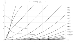
It's the PC900/6HM5, a (semi) remote cutoff triode. For such triodes, the curves at higher Va voltages are special shaped. The i5 is the first model which is able to mimic such characteristics with a satisfying result.
All PC900/6HM5 electrode constructions seen so far were identical (although from different companies), so I assume that there is only 1 construction existing for that tube, and so I skipped the both manufacturer letters in the suffix - no need to distinguish between companies for this tube.
BR Adrian
Code:*PC900 LTspice model based on the generic triode model from Adrian Immler, version i5 *A version log is at the end of this file *100h BurnIn of 5 Lorenz tubes, sample selection and measurements done in Febr. 2021 *Params fitted to the measured values by Adrian Immler, Nov. 2021 *The high fit quality is presented at adrianimmler.simplesite.com *History's best of tube decribing art (plus some new ideas) is merged to this new approach. *@ neg. Vg, Ia accuracy is similar to Koren models, and unrivaled for remote cutoff triodes *@ small neg. Vg, the "Anlauf" current is considered. *@ pos. Vg, Ig and Ia accuracy is on a unrivaled level (including neg. Va range!) *This offers new simulation possibilities like grid resistor bias, backward plate modulated stages, *Audion radio circuits, low voltage amps, guitar distortion stages or pulsed stages. *All PC900/6HM5 electrode designs found so far were identical => manufacturer not mentioned in the suffix * anode (plate) * | grid * | | cathode * | | | .subckt PC900.i5 A G K + params: *Parameters for space charge current Is (100% assigned to Ia @ Vg < 0) + mu = 156 ;Determines the voltage gain @ constant Ia + rad = 6k2 ;Differential anode resistance, set @ Iad and Vg=0V + Vct = 0.288 ;Offsets the Ia-traces on the Va axis. Electrode material's contact potential + kp = 270 ;Mimics the island effect + xs = 1.5 ;Determines the curve of the Ia traces. Typically between 1.2 and 1.8 + kIsr = 85m ;Va-indepedent part of the Is reduction when gridcurrent occurs + kvdg = 60 ;Va-depedent part of the Is reduction when gridcurrent occurs * *Parameters for assigning the space charge current to Ia and Ig @ Vg > 0 + kB = 0.16 ;Describes how fast Ia drops to zero when Va approaches zero. + radl = 780 ;Differential resistance for the Ia emission limit @ very small Va and Vg > 0 + tsh = 10 ;Ia transmission sharpness from 1th to 2nd Ia area. Keep between 3 and 20. Start with 20. + xl = 1.5 ;Exponent for the emission limit * *Parameters of the grid-cathode vacuum diode + kg = 170 ;Inverse scaling factor for the Va independent part of Ig (caution - interacts with xg!) + Vctg = -0.55 ;Offsets the log Ig-traces on the Vg axis. Electrode material's contact potential + xg = 1.1 ;Determines the curve of the Ig slope versus (positive) Vg and Va >> 0 + VT = 0.135 ;Log(Ig) slope @ Vg<0. VT=k/q*Tk (cathodes absolute temp, typically 1150K) + rTr = 0.55 ;ratio of VT for Igr. Typically 0.8 + kVT=0 ;Va dependant koeff. of VT + gft1 = 0.05 ;reduces the steering voltage around Vg=-Vg0, for finetuning purposes + gft1a= 0.3 ;reduces the steering voltage around Vg=-Vg=. Effect decreases with 1/(1+kB*Va) + gft2 = 0.2 ;finetunes the Igr drop @ incrasing Va and around Vg=-Vg0 * *Parameters for the caps + cag = 0p37 ;From datasheet + cak = 0p08 ;From datasheet + cgk = 3p3 ;From datasheet * *special purpose parameters + os = 1 ;Overall scaling factor, if a user wishes to simulate manufacturing tolerances + murc = 48 ;Mu of the remote cutoff triode + ksrc = 1k38 ;Inverse Iarc gain factor for the remote cuttoff triode + kprc = 106 ;Mimics the island effect for the remote cotoff triode + Vbatt = 0 ;heater battery voltage for direct heated battery triodes + Vdrmax = 100 ;max voltage of internal Vg drop, for convergence improvements * *Calculated parameters + Iad = {100/rad} ;Ia where the anode a.c. resistance is set according to rad. + ks = {pow(mu/(rad*xs*Iad**(1-1/xs)),-xs)} ;Reduces the unwished xs influence to the Ia slope + ksnom = {pow(mu/(rad*1.5*Iad**(1-1/1.5)),-1.5)} ;Sub-equation for calculating Vg0 + Vg0 = {Vct + (Iad*ks)**(1/xs) - (Iad*ksnom)**(2/3)} ;Reduces the xs influence to Vct. + kl = {pow(1/(radl*xl*Ild**(1-1/xl)),-xl)} ;Reduces the xl influence to the Ia slope @ small Va + Ild = {sqrt(radl)*1m} ;Current where the Il a.c. resistance is set according to radl. * *Space charge current model Rak A K 100G ;avoids "floating net" errors Bft ft 0 V=1/(1+pow(2*abs(v(G,Ki)+Vg0),3)) ;an auxiliary voltage to finetune the triode around Vg=-Vg0 Bggi GGi 0 V=(v(Gi,Ki)+Vg0)*(1/(1+kIsr*max(0, v(G,Ki)+Vg0))) - gft1*v(ft) - gft1a*v(ft)/(1+kB*v(Ahc)) ;Effective internal grid voltage. Bahc Ahc 0 V=uramp(v(A,Ki)) ;Anode voltage, hard cut to zero @ neg. value Bst St 0 V=uramp(max(v(GGi)+v(A,Ki)/(mu), v(A,Ki)/kp*ln(1+exp(kp*(1/mu+v(GGi)/(1+v(Ahc)))))));Steering volt. Bs Ai Ki I=os/ks*pow(v(St),xs) ;Langmuir-Childs law for the space charge current Is Bstrc Strc 0 V=uramp(max(v(GGi)+v(Ahc)/(murc), v(Ahc)/kprc*ln(1+exp(kprc*(1/murc+v(GGi)/(1+v(Ahc)))))));FOR REMOTE CUTOFF TUBES ONLY Bsrc Ai Ki I=os/ksrc*pow(v(Strc),xs) ;FOR REMOTE CUTOFF TUBES ONLY * *Anode current limit @ small Va .func smin(z,y,k) {pow(pow(z+1f, -k)+pow(y+1f, -k), -1/k)} ;Min-function with smooth trans. .func ssmin(z,y,k) {min(min(z,y), smin(z*1.003,y*1.003,k))};smin-function which suppresses small residual differencies Ra A Ai 1 Bgl Gi A I=uramp(i(Ra)-ssmin(1/kl*pow(v(Ahc),xl),i(Ra),tsh)) ;Ia emission limit * *Grid model Rgk G K 10G ;avoids "floating net" errors Bvdg G Gi I=1/kvdg*pow(v(G,Gi),1.5) ;Reduces the internal effective grid voltage when Ig rises Bcoh G Gi I=pow(uramp(v(G,Gi)-Vdrmax),2) ;A convergence help which softly limits the internal Vg voltage drop. Rgip G Gi 1G ;avoids some warnings .func fVT() {VT*exp(-kVT*sqrt(v(A,Ki)))} .func Ivd(Vvd, kvd, xvd, VTvd) {if(Vvd < 3, 1/kvd*pow(VTvd*xvd*ln(1+exp(Vvd/VTvd/xvd)),xvd), 1/kvd*pow(Vvd, xvd))} ;Vacuum diode function Bgvd G Ki I=Ivd(v(G,Ki) + Vctg + min(0,v(A,Ki)/mu), kg/os, xg, fVT()) ;limits the internal Vg for convergence reasons Bstn Stn 0 V=v(GGi)+min(0,v(A,Ki))/mu ;special steering voltage, sensitive to negative Anodevoltages only *Bgr Gi Ai I= ivd(v(Stn),ks/os, xs, rTr*fVT())/(1+(kB+v(ft)*gft2)*v(Ahc));Is reflection to grid when Va approaches zero Bgr Gi Ai I=(ivd(v(Stn),ks/os, xs, rTr*fVT())+os/ksrc*pow(v(GGi),xs))/(1+(kB+v(ft)*gft2)*v(Ahc));FOR REMOTE CUTOFF TUBES ONLY Bs0 Ai Ki I=uramp(ivd(v(Stn),ks/os, xs, rTr*fVT()) - os/ks*pow(v(Stn),xs)) Bbatt Ki K V=Vbatt/2 ;for battery heated triodes; Offsets the average cathode potential to the half heater battery voltage * *Caps C1 A G {cag} C2 A K {cak} C3 G K {cgk} .ends * *Version log *i1 :Initial version *i2 :Pin order changed to the more common order A G K (Thanks to Markus Gyger for his tip) *i3 :bugfix of the Ivd-function: now also usable for larger Vvd *i4: Rgi replaced by a virtual vacuum diode (better convergence). ft1 deleted (no longer needed) ;2 new prarams for Ig finetuning @ Va and Vg near zero. New overall skaling factor os for aging etc. *i5: improved convergence performance. PosVg/NegVa area now correct. Also accurate now for remote cutoff triodes!
First of all, thank you for all work and efforts you do by sharing the result of your work here for the community!
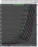
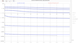
I'm using your PC900.i5 model to do some simulations (got several PC900, would like to use them for something). I get a mismatch on the grid-plate transfer characteristic (sorry for the busy pic):
At 200V plate and -1.6V grid I get around 10mA on simulation, while the PC900 Philips datasheet shows that the bias at that anode current and voltage should be around -2.2V. I'm probably doing something wrong, but can't find what. Any ideas what would be the issue?
Best regards,
Jose
Hi Jose
My i5 and i6 models are all based on measured samples. While you compare my pc900 model with the data sheet. Main advantage is, that my models provide a grid current model of good quality. Especially for guitar amps with overdriven stages, reliable gris current models are appreciated.
To find the best representative tube, I do the following procedure:
1) burn in a bunch of tubes (typically 10 triodes) at 70% allowed plate losses, for 100 hours
2) Measure all of them
3) Analyze the curves in terms of plate resistance, contact voltage, mu, island effect and grid current. Select one of the triode as the "golden Sample", which is the most average in all those aspects.
4) Measure again the golden sample under hot conditions (done with the i6 only), as some tubes show curve drifts when they get hot.
5) Create a spice model according to those curves.
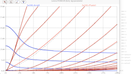
I recently measured my PC900 golden sample again, under hot conditions. It showed a bit different curves, closer to the data sheet curves. For the bias point you mentioned, this means Vg=-1.8V when hot, and -1.6V when cold. See attached graph.
A drawback of my approach which can't be solved is, that the golden sample is actually representative for the BATCH from where my bunch of tubes belongs to. Tubs from other batches might show a bit different curves.
BR Adrian
My i5 and i6 models are all based on measured samples. While you compare my pc900 model with the data sheet. Main advantage is, that my models provide a grid current model of good quality. Especially for guitar amps with overdriven stages, reliable gris current models are appreciated.
To find the best representative tube, I do the following procedure:
1) burn in a bunch of tubes (typically 10 triodes) at 70% allowed plate losses, for 100 hours
2) Measure all of them
3) Analyze the curves in terms of plate resistance, contact voltage, mu, island effect and grid current. Select one of the triode as the "golden Sample", which is the most average in all those aspects.
4) Measure again the golden sample under hot conditions (done with the i6 only), as some tubes show curve drifts when they get hot.
5) Create a spice model according to those curves.
I recently measured my PC900 golden sample again, under hot conditions. It showed a bit different curves, closer to the data sheet curves. For the bias point you mentioned, this means Vg=-1.8V when hot, and -1.6V when cold. See attached graph.
A drawback of my approach which can't be solved is, that the golden sample is actually representative for the BATCH from where my bunch of tubes belongs to. Tubs from other batches might show a bit different curves.
BR Adrian
Attachments
PC900 model based on Philips PC900 for sharing and improvement:
Code:
** Advanced Grid Current **********************************
* Created on 07/03/2023 23:25 using paint_kit.jar 3.1
* www.dmitrynizh.com/tubeparams_image.htm
* Plate Curves image file: pc900adr.png
* Data source link: PC900.png
*----------------------------------------------------------------------------------
.SUBCKT PC900 1 2 3 ; Plate Grid Cathode
+ PARAMS: CCG=3.3P  CGP=0.08P CCP=1.9P
+ MU=2352.1 KG1=41.16 KP=154.36 KVB=1934.68 VCT=-8.004E-4 EX=1.055
+ VGOFF=-0.6 IGA=1.572E-5 IGB=0.00459 IGC=56.16 IGEX=1.426
* Vp_MAX=300 Ip_MAX=40 Vg_step=0.5 Vg_start=1 Vg_count=16
* Rp=4000 Vg_ac=55 P_max=2.2 Vg_qui=-48 Vp_qui=300
* X_MIN=45 Y_MIN=21 X_SIZE=829 Y_SIZE=555 FSZ_X=1296 FSZ_Y=736 XYGrid=true
* showLoadLine=n showIp=y isDHT=n isPP=n isAsymPP=n showDissipLimit=y
* showIg1=y gridLevel2=y isInputSnapped=n
* XYProjections=n harmonicPlot=n dissipPlot=n
*----------------------------------------------------------------------------------
E1 7 0 VALUE={V(1,3)/KP*LOG(1+EXP(KP*(1/MU+(VCT+V(2,3))/SQRT(KVB+V(1,3)*V(1,3)))))}
RE1 7 0 1G  ; TO AVOID FLOATING NODES
G1 1 3 VALUE={(PWR(V(7),EX)+PWRS(V(7),EX))/KG1}
RCP 1 3 1G   ; TO AVOID FLOATING NODES
C1 2 3 {CCG} ; CATHODE-GRID
C2 2 1 {CGP} ; GRID=PLATE
C3 1 3 {CCP} ; CATHODE-PLATE
RE2 2 0 1G
EGC 8 0 VALUE={V(2,3)-VGOFF} ; POSITIVE GRID THRESHOLD
GG 2 3 VALUE={(IGA+IGB/(IGC+V(1,3)))*(MU/KG1)*(PWR(V(8),IGEX)+PWRS(V(8),IGEX))}
.ENDS
*$
Attachments
 Some posts have been removed. You are asked to confine discussion to the topic at hand. Further action may be taken as we see fit.
Thank you Koown! The transfer curves match the datasheet I got.PC900 model based on Philips PC900 for sharing and improvement:
Code:** Advanced Grid Current ********************************** * Created on 07/03/2023 23:25 using paint_kit.jar 3.1 * www.dmitrynizh.com/tubeparams_image.htm * Plate Curves image file: pc900adr.png * Data source link: PC900.png *---------------------------------------------------------------------------------- .SUBCKT PC900 1 2 3 ; Plate Grid Cathode + PARAMS: CCG=3.3P CGP=0.08P CCP=1.9P + MU=2352.1 KG1=41.16 KP=154.36 KVB=1934.68 VCT=-8.004E-4 EX=1.055 + VGOFF=-0.6 IGA=1.572E-5 IGB=0.00459 IGC=56.16 IGEX=1.426 * Vp_MAX=300 Ip_MAX=40 Vg_step=0.5 Vg_start=1 Vg_count=16 * Rp=4000 Vg_ac=55 P_max=2.2 Vg_qui=-48 Vp_qui=300 * X_MIN=45 Y_MIN=21 X_SIZE=829 Y_SIZE=555 FSZ_X=1296 FSZ_Y=736 XYGrid=true * showLoadLine=n showIp=y isDHT=n isPP=n isAsymPP=n showDissipLimit=y * showIg1=y gridLevel2=y isInputSnapped=n * XYProjections=n harmonicPlot=n dissipPlot=n *---------------------------------------------------------------------------------- E1 7 0 VALUE={V(1,3)/KP*LOG(1+EXP(KP*(1/MU+(VCT+V(2,3))/SQRT(KVB+V(1,3)*V(1,3)))))} RE1 7 0 1G ; TO AVOID FLOATING NODES G1 1 3 VALUE={(PWR(V(7),EX)+PWRS(V(7),EX))/KG1} RCP 1 3 1G ; TO AVOID FLOATING NODES C1 2 3 {CCG} ; CATHODE-GRID C2 2 1 {CGP} ; GRID=PLATE C3 1 3 {CCP} ; CATHODE-PLATE RE2 2 0 1G EGC 8 0 VALUE={V(2,3)-VGOFF} ; POSITIVE GRID THRESHOLD GG 2 3 VALUE={(IGA+IGB/(IGC+V(1,3)))*(MU/KG1)*(PWR(V(8),IGEX)+PWRS(V(8),IGEX))} .ENDS *$
Hi all
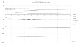
As mentioned above, my PC900 golden sample showed different curves when hot. So, I decided to create a new model from the hot curves.
I took quite a bit of time to create it because it is actually made of two triodes in parallel (a high mu & gm one, and a low mu & gm one), which means a highly iterative tuning process.
Thanks to its internal two-triode arrangement, my model mimics the remote cutoff behavior of the PC900. This means one can simulate automatic gain control circuits, for what the PC900 was intended for.
BR Adrian
Code:
*PC900 LTspice model based on the generic triode model from Adrian Immler, version i6
*A version log is at the end of this file
*100h BurnIn of 5 Lorenz tubes, sample selection and measurements done in May 2023
*Params fitted to the measured values by Adrian Immler, July 2023
*The high fit quality is presented at adrianimmler.simplesite.com
*History's best of tube decribing art (plus some new ideas) is merged to this new approach.
*@ neg. Vg, Ia accuracy is similar to Koren models, and unrivaled for remote cutoff triodes
*@ small neg. Vg, the "Anlauf" current is considered.
*@ pos. Vg, Ig and Ia accuracy is on a unrivaled level (including neg. Va range!)
*This offers new simulation possibilities like grid resistor bias, backward plate modulated stages,
*Audion radio circuits, low voltage amps, guitar distortion stages or pulsed stages.
*All PC900/6HM5 electrode designs found so far were identical => manufacturer not mentioned in the suffix
*                anode (plate)
*                | grid
*                | | cathode
*                | | |
.subckt PC900.i6 A G K
+ params:
*Parameters for space charge current Is (100% assigned to Ia @ Vg < 0)
+ mu   = 146   ;Determines the voltage gain @ constant Ia
+ rad  = 5k0   ;Differential anode resistance, set @ Iad and Vg=0V
+ Vct  = 0.2   ;Offsets the Ia-traces on the Va axis. Electrode material's contact potential
+ kp   = 230   ;Mimics the island effect
+ xs   = 1.5   ;Determines the curve of the Ia traces. Typically between 1.2 and 1.8
+ kIsr = 50m   ;Va-indepedent part of the Is reduction when gridcurrent occurs
+ kvdg  = 57   ;Va-depedent part of the Is reduction when gridcurrent occurs
*
*Parameters for assigning the space charge current to Ia and Ig @ Vg > 0
+ kB   = 0.16  ;Describes how fast Ia drops to zero when Va approaches zero.
+ radl = 770   ;Differential resistance for the Ia emission limit @ very small Va and Vg > 0
+ tsh  = 7     ;Ia transmission sharpness from 1th to 2nd Ia area. Keep between 3 and 20. Start with 20.
+ xl   = 1.5   ;Exponent for the emission limit
*
*Parameters of the grid-cathode vacuum diode
+ kg = 129     ;Inverse scaling factor for the Va independent part of Ig (caution - interacts with xg!)
+ Vctg = -0.55 ;Offsets the log Ig-traces on the Vg axis. Electrode material's contact potential
+ xg   = 1.00  ;Determines the curve of the Ig slope versus (positive) Vg and Va >> 0
+ VT   = 0.143 ;Log(Ig) slope @ Vg<0. VT=k/q*Tk (cathodes absolute temp, typically 1150K)
+ rTr  = 0.55  ;ratio of VT for Igr. Typically 0.8
+ kVT=0        ;Va dependant koeff. of VT
+ gft1 = 0     ;reduces the steering voltage around Vg=-Vg0, for finetuning purposes
+ gft1a= 0.23  ;reduces the steering voltage around Vg=-Vg=. Effect decreases with 1/(1+kB*Va)
+ gft2 = 0.52  ;finetunes the Igr drop @ incrasing Va and around Vg=-Vg0
*
*Parameters for the caps
+ cag  = 0p37  ;From datasheet
+ cak  = 0p08  ;From datasheet
+ cgk  = 3p3   ;From datasheet
*
*special purpose parameters
+ os = 1       ;Overall scaling factor, if a user wishes to simulate manufacturing tolerances
+ murc = 30    ;Mu of the remote cutoff triode
+ ksrc = 3k3   ;Inverse Iarc gain factor for the remote cuttoff triode
+ kprc = 130   ;Mimics the island effect for the remote cotoff triode
+ Vbatt = 0    ;heater battery voltage for direct heated battery triodes
+ Vdrmax = 0.85;max voltage of internal Vg drop, for convergence improvements
*
*Calculated parameters
+ Iad = {100/rad} ;Ia where the anode a.c. resistance is set according to rad.
+ ks = {pow(mu/(rad*xs*Iad**(1-1/xs)),-xs)} ;Reduces the unwished xs influence to the Ia slope
+ ksnom = {pow(mu/(rad*1.5*Iad**(1-1/1.5)),-1.5)} ;Sub-equation for calculating Vg0
+ Vg0 = {Vct + (Iad*ks)**(1/xs) - (Iad*ksnom)**(2/3)} ;Reduces the xs influence to Vct.
+ kl = {pow(1/(radl*xl*Ild**(1-1/xl)),-xl)} ;Reduces the xl influence to the Ia slope @ small Va
+ Ild = {sqrt(radl)*1m} ;Current where the Il a.c. resistance is set according to radl.
*
*Space charge current model
Rak A K 100G ;avoids "floating net" errors
Bft   ft 0 V=1/(1+pow(2*abs(v(G,Ki)+Vg0),3)) ;an auxiliary voltage to finetune the triode around Vg=-Vg0
Bggi GGi 0 V=(v(Gi,Ki)+Vg0)*(1/(1+kIsr*max(0, v(G,Ki)+Vg0))) - gft1*v(ft) - gft1a*v(ft)/(1+kB*v(Ahc)) ;Effective internal grid voltage.
Bahc Ahc 0 V=uramp(v(A,Ki)) ;Anode voltage, hard cut to zero @ neg. value
Bst   St 0 V=uramp(max(v(GGi)+v(A,Ki)/(mu), v(A,Ki)/kp*ln(1+exp(kp*(1/mu+v(GGi)/(1+v(Ahc)))))));Steering volt.
Bs    Ai Ki I=os/ks*pow(v(St),xs) ;Langmuir-Childs law for the space charge current Is
Bstrc Strc 0 V=uramp(max(v(GGi)+v(Ahc)/(murc), v(Ahc)/kprc*ln(1+exp(kprc*(1/murc+v(GGi)/(1+v(Ahc)))))));FOR REMOTE CUTOFF TUBES ONLY
Bsrc   Ai Ki I=os/ksrc*pow(v(Strc),xs) ;FOR REMOTE CUTOFF TUBES ONLY
*
*Anode current limit @ small Va
.func smin(z,y,k) {pow(pow(z+1f, -k)+pow(y+1f, -k), -1/k)} ;Min-function with smooth trans.
.func ssmin(z,y,k) {min(min(z,y), smin(z*1.003,y*1.003,k))};smin-function which suppresses small residual differencies
Ra  A Ai 1
Bgl Gi A I=uramp(i(Ra)-ssmin(1/kl*pow(v(Ahc),xl),i(Ra),tsh)) ;Ia emission limit
*
*Grid model
Rgk G K 10G ;avoids "floating net" errors
Bvdg G Gi I=1/kvdg*pow(v(G,Gi),1.5) ;Reduces the internal effective grid voltage when Ig rises
Bcoh G Gi I=pow(uramp(v(G,Gi)-Vdrmax),2) ;A convergence help which softly limits the internal Vg voltage drop.
Rgip G Gi 1G ;avoids some warnings
.func fVT() {VT*exp(-kVT*sqrt(v(A,Ki)))}
.func Ivd(Vvd, kvd, xvd, VTvd)  {if(Vvd < 3, 1/kvd*pow(VTvd*xvd*ln(1+exp(Vvd/VTvd/xvd)),xvd), 1/kvd*pow(Vvd, xvd))} ;Vacuum diode function
Bgvd G Ki I=Ivd(v(G,Ki) + Vctg + min(0,v(A,Ki)/mu), kg/os, xg, fVT()) ;limits the internal Vg for convergence reasons
Bstn Stn 0 V=v(GGi)+min(0,v(A,Ki))/mu ;special steering voltage, sensitive to negative Anodevoltages only
*Bgr Gi Ai I= ivd(v(Stn),ks/os, xs, rTr*fVT())/(1+(kB+v(ft)*gft2)*v(Ahc));Is reflection to grid when Va approaches zero
Bgr Gi Ai I=(ivd(v(Stn),ks/os, xs, rTr*fVT())+os/ksrc*pow(v(GGi),xs))/(1+(kB+v(ft)*gft2)*v(Ahc));FOR REMOTE CUTOFF TUBES ONLY
Bs0 Ai Ki  I=uramp(ivd(v(Stn),ks/os, xs, rTr*fVT()) - os/ks*pow(v(Stn),xs))
Bbatt Ki K V=Vbatt/2 ;for battery heated triodes; Offsets the average cathode potential to the half heater battery voltage
*
*Caps
C1 A G {cag}
C2 A K {cak}
C3 G K {cgk}
.ends
*
*Version log
*i1 :Initial version
*i2 :Pin order changed to the more common order A G K (Thanks to Markus Gyger for his tip)
*i3 :bugfix of the Ivd-function: now also usable for larger Vvd
*i4: Rgi replaced by a virtual vacuum diode (better convergence). ft1 deleted (no longer needed)
;2 new prarams for Ig finetuning @ Va and Vg near zero. New overall skaling factor os for aging etc.
*i5: improved convergence performance. PosVg/NegVa area now correct. Also accurate now for remote cutoff triodes!
*i6: like i5, but created from HOT measured tubes.
Attachments
- Home
- Amplifiers
- Tubes / Valves
- Vacuum Tube SPICE Models