Does anyone have a model for a 2A3 or other DHT tube that include both cathode pins? Or is there a reason no one does that? I would like to model a circuit change that reduces DHT hum more than the hum pot already in the amp but it involves both pins, so I'm not sure how to model that with only the standard K represented.
Apologies if this is getting off-topic. I'll also look for another place to ask for help, but this thread seemed to have the tube modeling covered.
Thanks in advance.
Apologies if this is getting off-topic. I'll also look for another place to ask for help, but this thread seemed to have the tube modeling covered.
Thanks in advance.
This is the right place, I think you are looking for a model with a filament, I am pretty sure they exist but I am not entirely sure they simulate the AC behaviors of a filamentary cathode correctly.
Perhaps you can simulate this by using a resistive voltage divider with the cathode connected in the center. The resistors should match the warm DCR of the filament. (you can calculate that with ohms on a heated tube, or just calculate it from the listed operating current and voltage.) You can make the resistance values slightly assymettrical to move the virtual cathode around a bit. I have no idea whether this is useful or not, but it is all I can think of.
Perhaps you can simulate this by using a resistive voltage divider with the cathode connected in the center. The resistors should match the warm DCR of the filament. (you can calculate that with ohms on a heated tube, or just calculate it from the listed operating current and voltage.) You can make the resistance values slightly assymettrical to move the virtual cathode around a bit. I have no idea whether this is useful or not, but it is all I can think of.
This might be close to what you are looking for:Does anyone have a model for a 2A3 or other DHT tube that include both cathode pins?
https://www.bartola.co.uk/valves/2016/01/23/801a-dht-triode-spice-model/
I haven't played with this model myself but the SUBCKT does model the plate, grid, and both cathode terminals for the 801a triode.
Last edited:
I appreciate the quick reply @kevinkr !
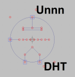
Not having a good model yet, I hadn't drawn this up. This pic is from the schematic of the amp I want to modify. I built it a couple of years ago and I love it, but in a small listening room with pretty efficient speakers, the hum has gotten to be too much for me.
I think you're suggestion makes sense. I'd basically pull the filament pins "Out of the symbol", attach them to the resistive-divider and take the 2.5V AC out of the center to K in a standard triode symbol. Then the hum pot in the original schematic attaches to the outside of the divider as well as the heater voltage.
I'll try to work up a simulation with that idea using one of the several 2A3 models in this thread and see if I can get the DHT hum to show up.
Thanks for the input. I'm brand new to LTSpice and modeling in general, so this is very helpful.
I'm going to go OT for a moment and recommend Rod Coleman's (Lyima) DHT heater regs, they really work and I have never felt they degraded the sound in any way. I guess I have been using them for at least 14 years now. They're not even expensive and they will solve the problem and eliminate the intermodulation distortion inherent with heating DHTs with AC. (I use them with GM70, 300B, EML20B, and others.)
@Fidget
To use Ale's 801a SPICE model you will need a new symbol, since the model has four pins and the LTspice built-in triode symbol has only three. I've thrown together a symbol that is compatible with the 801a SPICE model. It is attached here.
In LTspice, symbol files have the .asy file extension. The forum won't allow uploading .asy files so the attached file is named DHT.asy.txt. Delete the .txt extension before trying to use it.
I hope this is helpful.

Attachments
Are you read Dmitry Nizhegorodov articles?
https://www.dmitrynizh.com/dht-filament-hum-cancel.htm
He made "four pin" composite models for many DHTs.
http://www.dmitrynizh.com/composite-triode-models.htm
library: http://www.dmitrynizh.com/dmitry_composites.zip
These models are the base of newer models that we use in Spice simulations.
https://www.dmitrynizh.com/dht-filament-hum-cancel.htm
He made "four pin" composite models for many DHTs.
http://www.dmitrynizh.com/composite-triode-models.htm
library: http://www.dmitrynizh.com/dmitry_composites.zip
These models are the base of newer models that we use in Spice simulations.
Thanks for the symbol, @Ray Waters. I was able to get that part done before stopping by here. Learning LTSpice has been a little frustrating because I'm a Mac guy and not everything works quite as well as it does on Windows. But it's been a lot of fun, too. I'm starting to make real progress and think I'll be productive by this weekend.
@euro21, I didn't know about those. I'll certainly check them out next. Thanks a lot!
@euro21, I didn't know about those. I'll certainly check them out next. Thanks a lot!
Here are Ayumi models (both pentode and triode connected):
PENTODE:
TRIODE CONNECTED:
PENTODE:
Code:
*
* Generic pentode model: 6SH7
* Copyright 2003--2008 by Ayumi Nakabayashi, All rights reserved.
* Version 3.10, Generated on Sat Mar  8 22:40:54 2008
*            Plate
*            | Screen Grid
*            | |  Control Grid
*            | |  |  Cathode
*            | |  |  |
.SUBCKT 6SH7 A G2 G1 K
BGG   GG   0 V=V(G1,K)+0.69566782
BM1   M1   0 V=(0.0053973753*(URAMP(V(G2,K))+1e-10))**-0.3342013
BM2   M2   0 V=(0.81779465*(URAMP(V(GG)+URAMP(V(G2,K))/33.758141)))**1.8342013
BP    P    0 V=0.0026548433*(URAMP(V(GG)+URAMP(V(G2,K))/41.279484))**1.5
BIK   IK   0 V=U(V(GG))*V(P)+(1-U(V(GG)))*0.0016073552*V(M1)*V(M2)
BIG   IG   0 V=0.0013274216*URAMP(V(G1,K))**1.5*(URAMP(V(G1,K))/(URAMP(V(A,K))+URAMP(V(G1,K)))*1.2+0.4)
BIK2  IK2  0 V=V(IK,IG)*(1-0.4*(EXP(-URAMP(V(A,K))/URAMP(V(G2,K))*15)-EXP(-15)))
BIG2T IG2T 0 V=V(IK2)*(0.73640106*(1-URAMP(V(A,K))/(URAMP(V(A,K))+10))**1.5+0.26359894)
BIK3  IK3  0 V=V(IK2)*(URAMP(V(A,K))+5465)/(URAMP(V(G2,K))+5465)
BIK4  IK4  0 V=V(IK3)-URAMP(V(IK3)-(0.0014244744*(URAMP(V(A,K))+URAMP(URAMP(V(G2,K))-URAMP(V(A,K))))**1.5))
BIP   IP   0 V=URAMP(V(IK4,IG2T)-URAMP(V(IK4,IG2T)-(0.0014244744*URAMP(V(A,K))**1.5)))
BIAK  A    K I=V(IP)+1e-10*V(A,K)
BIG2  G2   K I=URAMP(V(IK4,IP))
BIGK  G1   K I=V(IG)
* CAPS
CGA   G1  A  0.003p
CGK   G1  K  5.1p
C12   G1  G2 3.4p
CAK   A   K  7p
.ENDS
TRIODE CONNECTED:
Code:
*
* Generic triode model: 6SH7T
* Copyright 2003--2008 by Ayumi Nakabayashi, All rights reserved.
* Version 3.10, Generated on Sat Mar  8 22:40:54 2008
*             Plate
*             | Grid
*             | | Cathode
*             | | |
.SUBCKT 6SH7T A G K
BGG   GG   0 V=V(G,K)+0.69566782
BM1   M1   0 V=(0.0053973753*(URAMP(V(A,K))+1e-10))**-0.3342013
BM2   M2   0 V=(0.81779465*(URAMP(V(GG)+URAMP(V(A,K))/33.758141)+1e-10))**1.8342013
BP    P    0 V=0.0026548433*(URAMP(V(GG)+URAMP(V(A,K))/41.279484)+1e-10)**1.5
BIK   IK   0 V=U(V(GG))*V(P)+(1-U(V(GG)))*0.0016073552*V(M1)*V(M2)
BIG   IG   0 V=0.0013274216*URAMP(V(G,K))**1.5*(URAMP(V(G,K))/(URAMP(V(A,K))+URAMP(V(G,K)))*1.2+0.4)
BIAK  A    K I=URAMP(V(IK,IG)-URAMP(V(IK,IG)-(0.0014244744*URAMP(V(A,K))**1.5)))+1e-10*V(A,K)
BIGK  G    K I=V(IG)
* CAPS
CGA   G    A 3.4p
CGK   G    K 5.1p
CAK   A    K 7p
.ENDS1. Solved!
PSpice models for DHT hum results.
2. Not Solved!
There is no modeling in PSpice for the Intermodulation of 2X Power Mains Frequency on each and every music tone [or test tone, so you can more easily see it in a spectrum].
AC heating of DHT creates upper sidebands and lower sidebands on each music note, test tone, and other spectral lines (like the intrinsic 2nd and 3rd harmonic of a real musical instrument).
The sidebands are at 2X the Power Mains frequency.
Example:
100 Hz power mains
A French horn plays Concert A, 440Hz
The French horn's intrinsic music signal is 440Hz, 880Hz, and 1320Hz (and higher harmonics at a much lower level).
The 2X power mains sidebands appear at 440-100 = 340Hz; 440+100 = 540Hz; 880-100 = 780Hz; 880+100 = 980Hz;
1320-100 = 1220Hz; and 1320+100 = 1420Hz
Yes, those sidebands are many dB down from the signal.
Some things have not been simulated in PSpice.
I am not a fan of simulation (just my tinkering nature; and my general distaste of software interfaces).
Some people are very good at getting good results from simulations, especially those who know the items that the simulation does Not, and can Not, show them.
Make good measurements of a real circuit, and find the real results.
Just my decades of practice.
Your Mileage May Vary
Sorry about that. Try these; they are supposed to be Pspice compatible instead of LTspice, but I don't use Pspice so I can't test them to verify that.Thank you Ray,
I cannot run your Ayumi model, due to my PC just run the PSpice system.
PENTODE (Pspice)
Code:
*
* Generic pentode model: 6SH7
* Copyright 2003--2008 by Ayumi Nakabayashi, All rights reserved.
* Thanks to Tooru Kuroda.
* Version 3.10, Generated on Sat Mar  8 22:40:54 2008
*            Plate
*            | Screen Grid
*            | |  Control Grid
*            | |  |  Cathode
*            | |  |  |
.SUBCKT 6SH7 A G2 G1 K
.param GG  {(V(G1,K)+0.69566782)}
.param EP  {URAMP(V(A,K))}
.param EG  {URAMP(V(G1,K))}
.param EG2 {URAMP(V(G2,K))}
.param M1  {((0.0053973753*EG2)^-0.3342013)}
.param M2  {((0.81779465*URAMP(GG+EG2/33.758141))^1.8342013)}
.param P   {(0.0026548433*URAMP(GG+EG2/41.279484)^1.5)}
.param IK  {(U(GG)*P+(1-U(GG))*0.0016073552*M1*M2)}
.param IG  {(0.0013274216*EG^1.5*(EG/(EP+EG)*1.2+0.4))}
.param IK2 {((IK-IG)*(1-0.4*(EXP(-EP/(EG2+1e-10)*15)-EXP(-15))))}
.param IG2T {(IK2*(0.73640106*(1-EP/(EP+10))^1.5+0.26359894))}
.param IK3 {(IK2*(EP+5465)/(EG2+5465))}
.param IK4 {(IK3-URAMP(IK3-(0.0014244744*(EP+URAMP(EG2-EP))^1.5)))}
.param IP  {URAMP(IK4-IG2T-URAMP(IK4-IG2T-(0.0014244744*EP^1.5)))}
BIAK A  K I=IP+1e-10*V(A,K)
BIG2 G2 K I=URAMP(IK4-IP)
BIGK G1 K I=IG
* CAPS
CGA G1 A  0.003p
CGK G1 K  5.1p
C12 G1 G2 3.4p
CAK A  K  7p
.ENDS
TRIODE CONNECTED (Pspice):
Code:
*
* Generic triode model: 6SH7T
* Copyright 2003--2008 by Ayumi Nakabayashi, All rights reserved.
* Thanks to Tooru Kuroda.
* Version 3.10, Generated on Sat Mar  8 22:40:54 2008
*             Plate
*             | Grid
*             | | Cathode
*             | | |
.SUBCKT 6SH7T A G K
.param GG {(V(G,K)+0.69566782)}
.param EP {URAMP(V(A,K))}
.param EG {URAMP(V(G,K))}
.param M1 {((0.0053973753*EP)^-0.3342013)}
.param M2 {((0.81779465*URAMP(GG+EP/33.758141))^1.8342013)}
.param P  {(0.0026548433*URAMP(GG+EP/41.279484)^1.5)}
.param IK {(U(GG)*P+(1-U(GG))*0.0016073552*M1*M2)}
.param IG {(0.0013274216*EG^1.5*(EG/(EP+EG)*1.2+0.4))}
BIAK A K I=URAMP(IK-IG-URAMP(IK-IG-0.0014244744*EP^1.5))+1e-10*V(A,K)
BIGK G K I=IG
* CAPS
CGA G A 3.4p
CGK G K 5.1p
CAK A K 7p
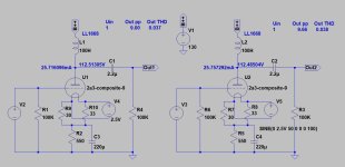
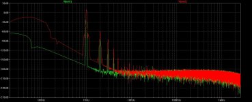
.ENDSIn LTSpice Dmitry "type" four pin DHT models "correctly" shows AC heating modulation.
This is the same (dissimilar -30R/33R- resistors as virtual cathode shows incorrect hum pot settings) preamp simulation with DC and AC filament heating.
The output FFT shows the intermodulation (sidebands around carrier and distortion products) in case of AC filament.


This is the same (dissimilar -30R/33R- resistors as virtual cathode shows incorrect hum pot settings) preamp simulation with DC and AC filament heating.
The output FFT shows the intermodulation (sidebands around carrier and distortion products) in case of AC filament.


euro21,
Great Job!
It shows the lower and upper sidebands are each offset from each tone, by 2x the power mains frequency . . . Correct.
You may be the first one who posted the screen shot results on diyAudio.
It should be noted that how far the sidebands are down (dBc) from the tone is dependent on two things:
1. The AC filament voltage versus the grid to filament bias voltage
2. The dBc is reduced (made worse) when the peak grid signal voltage and the peak AC filament voltage cause the grid to filament voltage
to get near or at the Contact Potential voltage.
The grid is still slightly more negative than the peak AC voltage at either end of the filament.
I am not talking about when the grid volts is the same as either end of the filament's peak volts. That is the zero volt condidion.
Thanks again, euro21
- Home
- Amplifiers
- Tubes / Valves
- Vacuum Tube SPICE Models

