Does anyone have LTSpice (or another Spice variety) models for the type 33 directly heated pentode? I've got a batch of them and want to think about how they might be used to drive 2A3 in the both pentode and triode mode.
Thanks!
Jeff
Thanks!
Jeff
Attachments
I've made this code for 6418 pentode using Java Paint KIP, but it refuse to work in my ltspice. Could anyone help?

Code:
.SUBCKT 6418_P P G2 G K ; LTSpice tetrode.asy pinout
* .SUBCKT 6418_P P G K G2 ; Koren Pentode Pspice pinout
+ PARAMS: MU=10.41 KG1=17952 KP=33.97 KVB=0.225 VCT=0.018 EX=1.484 KG2=1123.5 KNEE=14.88 KVC=2.57
+ KLAM=7.187E-9 KLAMG=0.006  KD=0.44 KC=0.14 KR1=0.0013 KR2=0.064 KVBG=0.015 KNK=-0.044 KNG=0.006
+ CCG=3P CGP=1.4P CCP=1.9P RGI=2000.0
* Vp_MAX=60 Ip_MAX=0.8 Vg_step=0.4 Vg_start=0 Vg_count=7
* X_MIN=816 Y_MIN=532 X_SIZE=1104 Y_SIZE=749 FSZ_X=2576 FSZ_Y=1456 XYGrid=true
* Rp=1400 Vg_ac=20 P_max=0.2 Vg_qui=-1.2 Vp_qui=300
* showLoadLine=n showIp=y isDHP=n isPP=n isAsymPP=n isUL=n showDissipLimit=y
* showIg1=n isInputSnapped=y addLocalNFB=n
* XYProjections=n harmonicPlot=y dissipPlot=n
* UL=0.43 EG2=22.5 gridLevel2=n addKink=n isTanhKnee=n advSigmoid=y
*----------------------------------------------------------------------------------
RE1  7 0  1G    ; DUMMY SO NODE 7 HAS 2 CONNECTIONS
E1   7 0  VALUE=  ; E1 BREAKS UP LONG EQUATION FOR G1.
+{V(G2,K)/KP*LOG(1+EXP((1/MU+(VCT+V(G,K))/SQRT(KVB+V(G2,K)*V(G2,K)))*KP))}
RE2  6 0  1G    ; DUMMY SO NODE 6 HAS 2 CONNECTIONS
E2  6 0  VALUE={(PWR(V(7),EX)+PWRS(V(7),EX))} ; Kg1 times KIT current
E4   8 0  VALUE={PWR(V(1,3)/KNEE/(V(6)*KVBG),2)}
E5   9 0  VALUE={SQRT(1-EXP(-V(8)*(KC+KR1*V(8))/(KD+KR2*V(8))))*1.5708}
RE4  8 0  1
RE5  9 0  1
G1   P K  VALUE={V(6)/KG1*V(9)*(1+KLAMG*V(P,K))+KLAM*V(P,K)}
G2   G2 K  VALUE={V(6)/KG2*(KVC-V(9))/(1+KLAMG*V(P,K))}
RCP  P K  1G     ; FOR CONVERGENCE
C1   K G  {CCG}  ; CATHODE-GRID 1
C2   G P  {CGP}  ; GRID 1-PLATE
C3   K P  {CCP}  ; CATHODE-PLATE
R1   G 5  {RGI}  ; FOR GRID CURRENT
D3   5 K  DX     ; FOR GRID CURRENT }
.MODEL DX D(IS=1N RS=1 CJO=10PF TT=1N)
.ENDS
*$Make sure "Kink" is checked. Aviod using "Advance Knee" if you can. The screen current is too high, need to adjust before it can be used.
Code:
**** 6418P ******************************************
* Created on 05/04/2023 22:50 using paint_kip.jar
* www.dmitrynizh.com/tubeparams_image.htm
* Plate Curves image file: 6418p.jpg
* Data source link: <plate curves URL>
*----------------------------------------------------------------------------------
.SUBCKT 6418P P G2 G K ; LTSpice tetrode.asy pinout
* .SUBCKT 6418P P G K G2 ; Koren Pentode Pspice pinout
+ PARAMS: MU=10.41 KG1=17952 KP=33.97 KVB=0.225 VCT=0.018 EX=1.484 KG2=1123.5 KNEE=4.464 KVC=2.57
+ KLAM=7.187E-9 KLAMG=0.006 KNEE2=3.4 KNEX=568.8  KNK=-0.044 KNG=0.006 KNPL=50 KNSL=11 KNPR=120 KNSR=29
+ CCG=3P CGP=1.4P CCP=1.9P RGI=2000.0
* Vp_MAX=60 Ip_MAX=0.8 Vg_step=0.4 Vg_start=0 Vg_count=7
* X_MIN=162 Y_MIN=231 X_SIZE=548 Y_SIZE=377 FSZ_X=1296 FSZ_Y=736 XYGrid=true
* Rp=1400 Vg_ac=20 P_max=0.2 Vg_qui=-1.2 Vp_qui=300
* showLoadLine=n showIp=y isDHP=n isPP=n isAsymPP=n isUL=n showDissipLimit=y
* showIg1=n isInputSnapped=y addLocalNFB=n
* XYProjections=n harmonicPlot=y dissipPlot=n
* UL=0.43 EG2=22.5 gridLevel2=n addKink=y isTanhKnee=y advSigmoid=n
*----------------------------------------------------------------------------------
RE1  7 0  1G    ; DUMMY SO NODE 7 HAS 2 CONNECTIONS
E1   7 0  VALUE=  ; E1 BREAKS UP LONG EQUATION FOR G1.
+{V(G2,K)/KP*LOG(1+EXP((1/MU+(VCT+V(G,K))/SQRT(KVB+V(G2,K)*V(G2,K)))*KP))}
RE2  6 0  1G    ; DUMMY SO NODE 6 HAS 2 CONNECTIONS
E2  6 0  VALUE={(PWR(V(7),EX)+PWRS(V(7),EX))} ; Kg1 times KIT current
RE21 21 0 1
E21  21 0 VALUE={V(6)/KG1*ATAN((V(P,K)+KNEX)/KNEE)*TANH(V(P,K)/KNEE2)} ; Ip with knee but no slope and no kink
RE22 22 0 1 ; E22: kink curr deviation for plate
E22  22 0 VALUE={V(21)*LIMIT(KNK-V(G,K)*KNG,0,0.3)*(-ATAN((V(P,K)-KNPL)/KNSL)+ATAN((V(P,K)-KNPR)/KNSR))}
G1   P  K  VALUE={V(21)*(1+KLAMG*V(P,K))+KLAM*V(P,K) + V(22)}
* Alexander Gurskii screen current, see audioXpress 2/2011, with slope and kink added
RE43 43 K 1G ; Dummy
E43  43 G2 VALUE={0} ; Dummy
G2   43 K  VALUE={V(6)/KG2*(KVC-ATAN((V(P,K)+KNEX)/KNEE)*TANH(V(P,K)/KNEE2))/(1+KLAMG*V(P,K))-V(22)}
RCP  P K  1G     ; FOR CONVERGENCE
C1   K G  {CCG}  ; CATHODE-GRID 1
C2   G P  {CGP}  ; GRID 1-PLATE
C3   K P  {CCP}  ; CATHODE-PLATE
R1   G 5  {RGI}  ; FOR GRID CURRENT
D3   5 K  DX     ; FOR GRID CURRENT }
.MODEL DX D(IS=1N RS=1 CJO=10PF TT=1N)
.ENDS
*$
Attachments
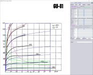
I have attached Model1_G2_600.jpg, which is your model but with S2 = 600 V; for comparison with your S2 = 500 V plot. Comparing it with the published S2 = 600 V data, it looks like model is still valid and accurate. Thanks very much for publishing this model.Gu81/ГУ81 pentode model for sharing:
Code:**** GU81 ****************************************** * Created on 02/17/2022 20:50 using paint_kip.jar * www.dmitrynizh.com/tubeparams_image.htm * Plate Curves image file: GU81.jpg * Data source link: <plate curves URL> *---------------------------------------------------------------------------------- .SUBCKT GU81 P G2 G K ; LTSpice tetrode.asy pinout * .SUBCKT GU81 P G K G2 ; Koren Pentode Pspice pinout + PARAMS: MU=3.222 KG1=2317.17 KP=56.18 KVB=12.01 VCT=-0.1625 EX=1.31 KG2=4863.69 KNEE=215.9 KVC=2.076 + KLAM=3.052E-14 KLAMG=2.803E-5 KNEE2=65.37 KNEX=166.47 KNK=3.763E-8 KNG=0.02817 KNPL=4.092E-9 KNSL=31537.46 KNPR=10600.24 KNSR=16388.67 + CCG=32P CGP=0.1P CCP=26P VGOFF=-0.6 IGA=0.001 IGB=0.465 IGC=1.68 IGEX=1.84 * Vp_MAX=3200 Ip_MAX=1600 Vg_step=80 Vg_start=80 Vg_count=17 * X_MIN=73 Y_MIN=24 X_SIZE=776 Y_SIZE=633 FSZ_X=1296 FSZ_Y=736 XYGrid=false * Rp=1400 Vg_ac=20 P_max=450 Vg_qui=-560 Vp_qui=300 * showLoadLine=n showIp=y isDHP=n isPP=n isAsymPP=n isUL=n showDissipLimit=y * showIg1=y isInputSnapped=y addLocalNFB=n * XYProjections=n harmonicPlot=y dissipPlot=n * UL=0.43 EG2=500 gridLevel2=y addKink=y isTanhKnee=y advSigmoid=n *---------------------------------------------------------------------------------- RE1 7 0 1G ; DUMMY SO NODE 7 HAS 2 CONNECTIONS E1 7 0 VALUE= ; E1 BREAKS UP LONG EQUATION FOR G1. +{V(G2,K)/KP*LOG(1+EXP((1/MU+(VCT+V(G,K))/SQRT(KVB+V(G2,K)*V(G2,K)))*KP))} RE2 6 0 1G ; DUMMY SO NODE 6 HAS 2 CONNECTIONS E2 6 0 VALUE={(PWR(V(7),EX)+PWRS(V(7),EX))} ; Kg1 times KIT current RE21 21 0 1 E21 21 0 VALUE={V(6)/KG1*ATAN((V(P,K)+KNEX)/KNEE)*TANH(V(P,K)/KNEE2)} ; Ip with knee but no slope and no kink RE22 22 0 1 ; E22: kink curr deviation for plate E22 22 0 VALUE={V(21)*LIMIT(KNK-V(G,K)*KNG,0,0.3)*(-ATAN((V(P,K)-KNPL)/KNSL)+ATAN((V(P,K)-KNPR)/KNSR))} G1 P K VALUE={V(21)*(1+KLAMG*V(P,K))+KLAM*V(P,K) + V(22)} * Alexander Gurskii screen current, see audioXpress 2/2011, with slope and kink added RE43 43 K 1G ; Dummy E43 43 G2 VALUE={0} ; Dummy G2 43 K VALUE={V(6)/KG2*(KVC-ATAN((V(P,K)+KNEX)/KNEE)*TANH(V(P,K)/KNEE2))/(1+KLAMG*V(P,K))-V(22)} RCP P K 1G ; FOR CONVERGENCE C1 K G {CCG} ; CATHODE-GRID 1 C2 G P {CGP} ; GRID 1-PLATE C3 K P {CCP} ; CATHODE-PLATE RE23 G 0 1G GG G K VALUE={(IGA+IGB/(IGC+V(P,K)))*(MU/KG1)* +(PWR(V(G,K)-VGOFF,IGEX)+PWRS(V(G,K)-VGOFF,IGEX))} .ENDS *$
Attachments

Try this 33 RCA triode and pentode model:
Code:
**** 33_T ** Advanced Grid Current **********************************
* Created on 05/07/2023 22:22 using paint_kit.jar 3.1
* www.dmitrynizh.com/tubeparams_image.htm
* Plate Curves image file: 33-t.png
* Data source link:
*----------------------------------------------------------------------------------
.SUBCKT 33_T 1 2 3 ; Plate Grid Cathode
+ PARAMS: CCG=8P  CGP=1P CCP=12P
+ MU=4.929 KG1=2898.64 KP=66.26 KVB=156.53 VCT=-2.27 EX=1.236
+ VGOFF=-0.6 IGA=0.001 IGB=0.3 IGC=8 IGEX=2
* Vp_MAX=280 Ip_MAX=35 Vg_step=5 Vg_start=0 Vg_count=11
* Rp=4000 Vg_ac=55 P_max=2 Vg_qui=-48 Vp_qui=300
* X_MIN=24 Y_MIN=74 X_SIZE=809 Y_SIZE=410 FSZ_X=1296 FSZ_Y=736 XYGrid=false
* showLoadLine=n showIp=y isDHT=n isPP=n isAsymPP=n showDissipLimit=y
* showIg1=y gridLevel2=y isInputSnapped=n
* XYProjections=n harmonicPlot=n dissipPlot=n
*----------------------------------------------------------------------------------
E1 7 0 VALUE={V(1,3)/KP*LOG(1+EXP(KP*(1/MU+(VCT+V(2,3))/SQRT(KVB+V(1,3)*V(1,3)))))}
RE1 7 0 1G  ; TO AVOID FLOATING NODES
G1 1 3 VALUE={(PWR(V(7),EX)+PWRS(V(7),EX))/KG1}
RCP 1 3 1G   ; TO AVOID FLOATING NODES
C1 2 3 {CCG} ; CATHODE-GRID
C2 2 1 {CGP} ; GRID=PLATE
C3 1 3 {CCP} ; CATHODE-PLATE
RE2 2 0 1G
EGC 8 0 VALUE={V(2,3)-VGOFF} ; POSITIVE GRID THRESHOLD
GG 2 3 VALUE={(IGA+IGB/(IGC+V(1,3)))*(MU/KG1)*(PWR(V(8),IGEX)+PWRS(V(8),IGEX))}
.ENDS
*$
Code:
**** 33_P ******************************************
* Created on 05/07/2023 23:43 using paint_kip.jar
* www.dmitrynizh.com/tubeparams_image.htm
* Plate Curves image file: 33-p.gif
* Data source link: <plate curves URL>
*----------------------------------------------------------------------------------
.SUBCKT 33_P P G2 G K ; LTSpice tetrode.asy pinout
* .SUBCKT 33_P P G K G2 ; Koren Pentode Pspice pinout
+ PARAMS: MU=5.047 KG1=2098.8 KP=51.35 KVB=3514.37 VCT=-7.52 EX=1.052 KG2=2629.84 KNEE=0.15 KVC=1.601
+ KLAM=5.75E-8 KLAMG=4.811E-4  KD=0.2741 KC=7.383E-5 KR1=1.65E-7 KR2=0.0512 KVBG=4.125E-4 KB1=1.6 KB2=2 KB3=2 KB4=2.14 KVBGI=6.25E-6 KNK=0.43 KNG=1.276E-6 KNPL=0.07129 KNSL=0.008594 KNPR=36 KNSR=17.4
+ CCG=8P CGP=1P CCP=12P VGOFF=-0.6 IGA=0.001 IGB=0.3 IGC=8 IGEX=2
* Vp_MAX=400 Ip_MAX=70 Vg_step=10 Vg_start=0 Vg_count=9
* X_MIN=52 Y_MIN=73 X_SIZE=720 Y_SIZE=396 FSZ_X=1296 FSZ_Y=736 XYGrid=false
* Rp=1400 Vg_ac=20 P_max=5 Vg_qui=-40 Vp_qui=300
* showLoadLine=n showIp=y isDHP=n isPP=n isAsymPP=n isUL=n showDissipLimit=y
* showIg1=y isInputSnapped=y addLocalNFB=n
* XYProjections=n harmonicPlot=y dissipPlot=n
* UL=0.43 EG2=180 gridLevel2=y addKink=y isTanhKnee=n advSigmoid=y
*----------------------------------------------------------------------------------
RE1  7 0  1G    ; DUMMY SO NODE 7 HAS 2 CONNECTIONS
E1   7 0  VALUE=  ; E1 BREAKS UP LONG EQUATION FOR G1.
+{V(G2,K)/KP*LOG(1+EXP((1/MU+(VCT+V(G,K))/SQRT(KVB+V(G2,K)*V(G2,K)))*KP))}
RE2  6 0  1G    ; DUMMY SO NODE 6 HAS 2 CONNECTIONS
E2  6 0  VALUE={(PWR(V(7),EX)+PWRS(V(7),EX))} ; Kg1 times KIT current
E4   8 0  VALUE={V(P,K)/KNEE/(KVBGI+V(6)*KVBG)}
E5  81 0  VALUE={PWR(V(8),KB1)}
E6  82 0  VALUE={PWR(V(8),KB2)}
E7  83 0  VALUE={PWR(V(8),KB3)}
E8   9 0  VALUE={PWR(1-EXP(-V(81)*(KC+KR1*V(82))/(KD+KR2*V(83))),KB4)*1.5708}
RE4  8 0  1
RE5 81 0  1
RE6 82 0  1
RE7 83 0  1
RE8  9 0  1
RE21 21 0 1
E21  21 0 VALUE={V(6)/KG1*V(9)} ; Ip with knee but no slope and no kink
RE22 22 0 1 ; E22: kink curr deviation for plate
E22  22 0 VALUE={V(21)*LIMIT(KNK-V(G,K)*KNG,0,0.3)*(-ATAN((V(P,K)-KNPL)/KNSL)+ATAN((V(P,K)-KNPR)/KNSR))}
G1   P K  VALUE={V(21)*(1+KLAMG*V(P,K))+KLAM*V(P,K) + V(22)}
G2   G2 K  VALUE={V(6)/KG2*(KVC-V(9))/(1+KLAMG*V(P,K)) - V(22)}
RCP  P K  1G     ; FOR CONVERGENCE
C1   K G  {CCG}  ; CATHODE-GRID 1
C2   G P  {CGP}  ; GRID 1-PLATE
C3   K P  {CCP}  ; CATHODE-PLATE
RE23 G 0 1G
GG G K VALUE={(IGA+IGB/(IGC+V(P,K)))*(MU/KG1)*
+(PWR(V(G,K)-VGOFF,IGEX)+PWRS(V(G,K)-VGOFF,IGEX))}
.ENDS
*$
Attachments
Hello!
Has anyone seen a model for the triode part of the E/PCL84? I got a model for the pentode section, but can't find one for the triode section.
Thank you!
Jose
Has anyone seen a model for the triode part of the E/PCL84? I got a model for the pentode section, but can't find one for the triode section.
Thank you!
Jose
Try this for PCL84 triode section (only the datasheet for PCL84 has the triode curves)

**** TEST ******************************************
* Created on 05/11/2023 20:56 using paint_kit.jar 3.1
* www.dmitrynizh.com/tubeparams_image.htm
* Plate Curves image file:
* Data source link:
*----------------------------------------------------------------------------------
.SUBCKT PCL84T 1 2 3 ; Plate Grid Cathode
+ PARAMS: CCG=4P  CGP=2.7P CCP=2.3P RGI=2200
+ MU=89 KG1=400 KP=370 KVB=6000 VCT=-0.15 EX=1.464
* Vp_MAX=500 Ip_MAX=17.5 Vg_step=0.5 Vg_start=0 Vg_count=13
* Rp=4000 Vg_ac=55 P_max=1 Vg_qui=-48 Vp_qui=300
* X_MIN=243 Y_MIN=277 X_SIZE=633 Y_SIZE=438 FSZ_X=1519 FSZ_Y=969 XYGrid=true
* showLoadLine=n showIp=y isDHT=n isPP=n isAsymPP=n showDissipLimit=y
* showIg1=y gridLevel2=n isInputSnapped=n
* XYProjections=n harmonicPlot=n dissipPlot=n
*----------------------------------------------------------------------------------
E1 7 0 VALUE={V(1,3)/KP*LOG(1+EXP(KP*(1/MU+(VCT+V(2,3))/SQRT(KVB+V(1,3)*V(1,3)))))}
RE1 7 0 1G  ; TO AVOID FLOATING NODES
G1 1 3 VALUE={(PWR(V(7),EX)+PWRS(V(7),EX))/KG1}
RCP 1 3 1G   ; TO AVOID FLOATING NODES
C1 2 3 {CCG} ; CATHODE-GRID
C2 2 1 {CGP} ; GRID=PLATE
C3 1 3 {CCP} ; CATHODE-PLATE
D3 5 3 DX ; POSITIVE GRID CURRENT
R1 2 5 {RGI} ; POSITIVE GRID CURRENT
.MODEL DX D(IS=1N RS=1 CJO=10PF TT=1N)
.ENDS
*$
Try this for PCL84 triode section (only the datasheet for PCL84 has the triode curves)
** TEST ****************************************
.SUBCKT PCL84T 1 2 3 ; Plate Grid Cathode
E1 7 0 VALUE={V(1,3)/KP*LOG(1+EXP(KP*(1/MU+(VCT+V(2,3))/SQRT(KVB+V(1,3)*V(1,3)))))}
RE1 7 0 1G ; TO AVOID FLOATING NODES
G1 1 3 VALUE={(PWR(V(7),EX)+PWRS(V(7),EX))/KG1}
RCP 1 3 1G ; TO AVOID FLOATING NODES
C1 2 3 {CCG} ; CATHODE-GRID
C2 2 1 {CGP} ; GRID=PLATE
C3 1 3 {CCP} ; CATHODE-PLATE
D3 5 3 DX ; POSITIVE GRID CURRENT
R1 2 5 {RGI} ; POSITIVE GRID CURRENT
.MODEL DX D(IS=1N RS=1 CJO=10PF TT=1N)
.ENDS
*$
** TEST ****************************************
- Created on 05/11/2023 20:56 using paint_kit.jar 3.1
- www.dmitrynizh.com/tubeparams_image.htm
- Plate Curves image file:
- Data source link:
.SUBCKT PCL84T 1 2 3 ; Plate Grid Cathode
- PARAMS: CCG=4P CGP=2.7P CCP=2.3P RGI=2200
- MU=89 KG1=400 KP=370 KVB=6000 VCT=-0.15 EX=1.464
- Vp_MAX=500 Ip_MAX=17.5 Vg_step=0.5 Vg_start=0 Vg_count=13
- Rp=4000 Vg_ac=55 P_max=1 Vg_qui=-48 Vp_qui=300
- X_MIN=243 Y_MIN=277 X_SIZE=633 Y_SIZE=438 FSZ_X=1519 FSZ_Y=969 XYGrid=true
- showLoadLine=n showIp=y isDHT=n isPP=n isAsymPP=n showDissipLimit=y
- showIg1=y gridLevel2=n isInputSnapped=n
- XYProjections=n harmonicPlot=n dissipPlot=n
E1 7 0 VALUE={V(1,3)/KP*LOG(1+EXP(KP*(1/MU+(VCT+V(2,3))/SQRT(KVB+V(1,3)*V(1,3)))))}
RE1 7 0 1G ; TO AVOID FLOATING NODES
G1 1 3 VALUE={(PWR(V(7),EX)+PWRS(V(7),EX))/KG1}
RCP 1 3 1G ; TO AVOID FLOATING NODES
C1 2 3 {CCG} ; CATHODE-GRID
C2 2 1 {CGP} ; GRID=PLATE
C3 1 3 {CCP} ; CATHODE-PLATE
D3 5 3 DX ; POSITIVE GRID CURRENT
R1 2 5 {RGI} ; POSITIVE GRID CURRENT
.MODEL DX D(IS=1N RS=1 CJO=10PF TT=1N)
.ENDS
*$
Thank you very much, so far works quite well!Try this for PCL84 triode section (only the datasheet for PCL84 has the triode curves)
Try this 6П25Б (6P25B) model:
Code:
**** 6P25B ******************************************
* Created on 05/13/2023 20:57 using paint_kip.jar
* www.dmitrynizh.com/tubeparams_image.htm
* Plate Curves image file: 6P25B.png
* Data source link: <plate curves URL>
*----------------------------------------------------------------------------------
.SUBCKT 6P25B P G2 G K ; LTSpice tetrode.asy pinout
* .SUBCKT 6P25B P G K G2 ; Koren Pentode Pspice pinout
+ PARAMS: MU=7.268 KG1=1385.86 KP=29.56 KVB=12 VCT=0.2 EX=1.288 KG2=3931.2 KNEE=21.01 KVC=1.592
+ KLAM=1.18E-6 KLAMG=8.982E-4 KNEE2=9.32 KNEX=2.423  KNK=-0.2328 KNG=0.0383 KNPL=23.23 KNSL=10.45 KNPR=29.34 KNSR=34.62
+ CCG=6.7P CGP=6.2P CCP=0.8P VGOFF=-0.6 IGA=0.001 IGB=0.3 IGC=8 IGEX=2
* Vp_MAX=250 Ip_MAX=65 Vg_step=4 Vg_start=0 Vg_count=11
* X_MIN=36 Y_MIN=13 X_SIZE=803 Y_SIZE=519 FSZ_X=1296 FSZ_Y=736 XYGrid=true
* Rp=1400 Vg_ac=20 P_max=4.1 Vg_qui=-20 Vp_qui=300
* showLoadLine=n showIp=y isDHP=n isPP=n isAsymPP=n isUL=n showDissipLimit=y
* showIg1=y isInputSnapped=y addLocalNFB=n
* XYProjections=n harmonicPlot=y dissipPlot=n
* UL=0.43 EG2=110 gridLevel2=y addKink=y isTanhKnee=y advSigmoid=n
*----------------------------------------------------------------------------------
RE1  7 0  1G    ; DUMMY SO NODE 7 HAS 2 CONNECTIONS
E1   7 0  VALUE=  ; E1 BREAKS UP LONG EQUATION FOR G1.
+{V(G2,K)/KP*LOG(1+EXP((1/MU+(VCT+V(G,K))/SQRT(KVB+V(G2,K)*V(G2,K)))*KP))}
RE2  6 0  1G    ; DUMMY SO NODE 6 HAS 2 CONNECTIONS
E2  6 0  VALUE={(PWR(V(7),EX)+PWRS(V(7),EX))} ; Kg1 times KIT current
RE21 21 0 1
E21  21 0 VALUE={V(6)/KG1*ATAN((V(P,K)+KNEX)/KNEE)*TANH(V(P,K)/KNEE2)} ; Ip with knee but no slope and no kink
RE22 22 0 1 ; E22: kink curr deviation for plate
E22  22 0 VALUE={V(21)*LIMIT(KNK-V(G,K)*KNG,0,0.3)*(-ATAN((V(P,K)-KNPL)/KNSL)+ATAN((V(P,K)-KNPR)/KNSR))}
G1   P  K  VALUE={V(21)*(1+KLAMG*V(P,K))+KLAM*V(P,K) + V(22)}
* Alexander Gurskii screen current, see audioXpress 2/2011, with slope and kink added
RE43 43 K 1G ; Dummy
E43  43 G2 VALUE={0} ; Dummy
G2   43 K  VALUE={V(6)/KG2*(KVC-ATAN((V(P,K)+KNEX)/KNEE)*TANH(V(P,K)/KNEE2))/(1+KLAMG*V(P,K))-V(22)}
RCP  P K  1G     ; FOR CONVERGENCE
C1   K G  {CCG}  ; CATHODE-GRID 1
C2   G P  {CGP}  ; GRID 1-PLATE
C3   K P  {CCP}  ; CATHODE-PLATE
RE23 G 0 1G
GG G K VALUE={(IGA+IGB/(IGC+V(P,K)))*(MU/KG1)*
+(PWR(V(G,K)-VGOFF,IGEX)+PWRS(V(G,K)-VGOFF,IGEX))}
.ENDS
*$
Attachments

There is a misalignment of screen current curve which started at -4V, not 0V. Here is the correction:
Code:
**** 6P25B ******************************************
* Created on 05/14/2023 06:31 using paint_kip.jar
* www.dmitrynizh.com/tubeparams_image.htm
* Plate Curves image file: 6P25B.png
* Data source link: <plate curves URL>
*----------------------------------------------------------------------------------
.SUBCKT 6P25B P G2 G K ; LTSpice tetrode.asy pinout
* .SUBCKT 6P25B P G K G2 ; Koren Pentode Pspice pinout
+ PARAMS: MU=7.268 KG1=1385.86 KP=29.56 KVB=12 VCT=0.2 EX=1.288 KG2=2633.9 KNEE=21.01 KVC=1.592
+ KLAM=1.18E-6 KLAMG=8.982E-4 KNEE2=9.32 KNEX=2.423  KNK=-0.2328 KNG=0.0383 KNPL=23.23 KNSL=10.45 KNPR=29.34 KNSR=34.62
+ CCG=6.7P CGP=6.2P CCP=0.8P VGOFF=-0.6 IGA=0.001 IGB=0.3 IGC=8 IGEX=2
* Vp_MAX=250 Ip_MAX=65 Vg_step=4 Vg_start=0 Vg_count=11
* X_MIN=36 Y_MIN=13 X_SIZE=803 Y_SIZE=519 FSZ_X=1296 FSZ_Y=736 XYGrid=true
* Rp=1400 Vg_ac=20 P_max=4.1 Vg_qui=-20 Vp_qui=300
* showLoadLine=n showIp=y isDHP=n isPP=n isAsymPP=n isUL=n showDissipLimit=y
* showIg1=y isInputSnapped=y addLocalNFB=n
* XYProjections=n harmonicPlot=y dissipPlot=n
* UL=0.43 EG2=110 gridLevel2=y addKink=y isTanhKnee=y advSigmoid=n
*----------------------------------------------------------------------------------
RE1  7 0  1G    ; DUMMY SO NODE 7 HAS 2 CONNECTIONS
E1   7 0  VALUE=  ; E1 BREAKS UP LONG EQUATION FOR G1.
+{V(G2,K)/KP*LOG(1+EXP((1/MU+(VCT+V(G,K))/SQRT(KVB+V(G2,K)*V(G2,K)))*KP))}
RE2  6 0  1G    ; DUMMY SO NODE 6 HAS 2 CONNECTIONS
E2  6 0  VALUE={(PWR(V(7),EX)+PWRS(V(7),EX))} ; Kg1 times KIT current
RE21 21 0 1
E21  21 0 VALUE={V(6)/KG1*ATAN((V(P,K)+KNEX)/KNEE)*TANH(V(P,K)/KNEE2)} ; Ip with knee but no slope and no kink
RE22 22 0 1 ; E22: kink curr deviation for plate
E22  22 0 VALUE={V(21)*LIMIT(KNK-V(G,K)*KNG,0,0.3)*(-ATAN((V(P,K)-KNPL)/KNSL)+ATAN((V(P,K)-KNPR)/KNSR))}
G1   P  K  VALUE={V(21)*(1+KLAMG*V(P,K))+KLAM*V(P,K) + V(22)}
* Alexander Gurskii screen current, see audioXpress 2/2011, with slope and kink added
RE43 43 K 1G ; Dummy
E43  43 G2 VALUE={0} ; Dummy
G2   43 K  VALUE={V(6)/KG2*(KVC-ATAN((V(P,K)+KNEX)/KNEE)*TANH(V(P,K)/KNEE2))/(1+KLAMG*V(P,K))-V(22)}
RCP  P K  1G     ; FOR CONVERGENCE
C1   K G  {CCG}  ; CATHODE-GRID 1
C2   G P  {CGP}  ; GRID 1-PLATE
C3   K P  {CCP}  ; CATHODE-PLATE
RE23 G 0 1G
GG G K VALUE={(IGA+IGB/(IGC+V(P,K)))*(MU/KG1)*
+(PWR(V(G,K)-VGOFF,IGEX)+PWRS(V(G,K)-VGOFF,IGEX))}
.ENDS
*$
Attachments
Thanks! You mean screen current in my model, or in this one you provided?Make sure "Kink" is checked. Aviod using "Advance Knee" if you can. The screen current is too high, need to adjust before it can be used.
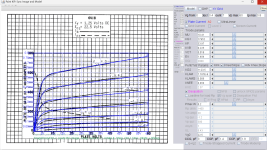
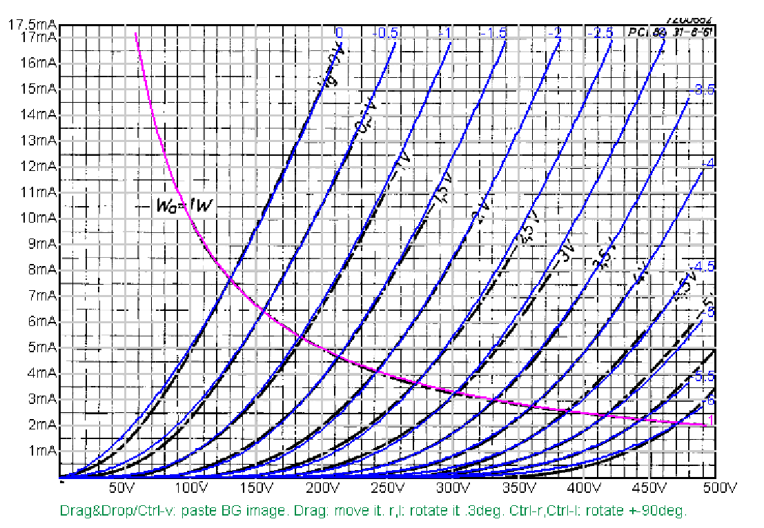
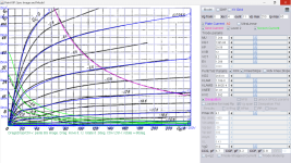
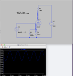
Thank you! I'll have to try that Paint-KIP program. Here's the screenshot of a basic test circuit of the 33 in triode mode, running the tube at about 132.4V/16.9mA. Gain is 10.Try this 33 RCA triode and pentode model:
To calculate the plate resistance, would we divide Vak by Ia?
132.4/.0169 = 7,834R
I've read that a rule of thumb for determining the value of the plate load resistor is that it should be roughly 3X the plate resistance. So I ran the model with a 24K load resistor and it needed a 550V supply for this op point.
Attachments
Please list the post numbers (at the top right of each post) of all the posts that you feel should be moved and also give a link to which thread those posts should be moved to.
List them in this thread and then report the post and we can move them.
Thanks

Moderator, would you please move posts 3655, thru 3678 to the following thread
https://www.diyaudio.com/community/threads/hv-pulse-amplifier-help-6bk4.399314/
You might want to leave a copy of 3655 and 3656 in the Vacuum Tube Spice Models category as I think they fit.
It might be wise to delete post 3676 and 3668 from the new position, as they will be out of context in the next thread.
Thanks, and sorry for going overboard in the wrong thread 🙂 Qmavam11
AKA Mikek
3A5 is an interesting little twin-triode. I can only find one very old model for it. Perhaps a better one can be made? I hope so. Would be fantastic.
Here's a set of plate curves from the Tung-Sol data sheet:


The Tung-Sol data sheet is here:
https://frank.pocnet.net/sheets/127/3/3A5.pdf
RCA data sheet is here:
https://frank.pocnet.net/sheets/049/3/3A5.pdf
Could be interesting...
Here's a set of plate curves from the Tung-Sol data sheet:
The Tung-Sol data sheet is here:
https://frank.pocnet.net/sheets/127/3/3A5.pdf
RCA data sheet is here:
https://frank.pocnet.net/sheets/049/3/3A5.pdf
Could be interesting...
- Home
- Amplifiers
- Tubes / Valves
- Vacuum Tube SPICE Models