The link I included in my post was different to your build in using Russian sub-miniature tubes instead of the ECC83 and EF86s, it is that change I was asking if anyone had tried? I already have the specified subminiature tubes so it may be worth a try.
BTW, I'll be using the amp with 16ohm speakers, which should give it a slightly easier life.[/QUOTE]
I know the variant with the subminiature Russian tubes but there are different characteristics and I suppose the need different static points to work properly.
I have seen some Polish OTL manufacturer using this but no details about were provided.
And yes, using 16 oms speakers, the power shall increase at 40 Watts, reducing the peak musical current and increasing the Pure A class at about 2 Watts.....NICE.
My first time here
Hello everybody! Thanks guys for interesting reading and ideas!
Like I have spent last year to make my own "Tim Mellow", I decided to share
the result with You all. Hopefully I will not make anything wrong with posting
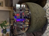
and can add some pictures of work done. BTW this thing is singing as an angel
together with ESS AMT-1C speakers. Any comments are welcome and sorry if my English is not the best...
And so: Ladies and Gentlemen - meet the Rolling Stone...
Hello everybody! Thanks guys for interesting reading and ideas!
Like I have spent last year to make my own "Tim Mellow", I decided to share
the result with You all. Hopefully I will not make anything wrong with posting
and can add some pictures of work done. BTW this thing is singing as an angel
together with ESS AMT-1C speakers. Any comments are welcome and sorry if my English is not the best...
And so: Ladies and Gentlemen - meet the Rolling Stone...
Attachments
Here is a cheap but safe and reliable transformer isolated differential probes for measuring symmetry of current in upper and lower banks of OTL output amp. I use 10W se transformer 5k to 32ohms but you can use any OT, for 32 ohms sec I can get about 4Vp-p in the output. This has helped me solves some of problems, like tube gain balance etc, hope you like it.
Attachments

Dear all, I've just began to buy all the needed components for this circuit.
Please forgive me if I can't read all the 41 pages of comments in this thread.. I also have a life.. .. .. anyway.. are there any "upgrades", good considerations compared to the very original article from AudioXpress ?
What I've already changed:
- bigger, flat, full aluminum (machined) case
- I'm just having my toroids made by a local company, ordering tomorrow or so. T1 (heating for noval tubes) will be wound with 9V secondaries, with 6.3V taps, so input tubes will get rectified-filtered DC heating, pentodes AC just like the original one
- I'm paying special attention to the voltage potencial differences between cathodes and heaters where applicable (so I'm also shifting heaters' potential according to original article)
- using a mechanical power-ON switch, which starts a microcontroller first. This microcontroller will then monitor a push-button (on/off in standby mode), while also take care of graceful start like the original article described.
- furthermore, I'll have a counter for usage hours for all different tube types and even for electrolitycs, so I can be warned by the microcontroller if some part is approaching end-of-life (e.g. 2000h, 5000h, whatever I set for more different devices I want)
- through proper isolation/coupling, it will also monitor some critical voltages
- and maybe adjust bias automatically (if needed - still thinking about that, or sticking to original article and leaving this as is)
- and having an OLED screen for all the goodies to display
- RCA input (through ALPS volume pot) + direct RCA input (bypassing pot, for DACs in PREamp mode) + direct XLR input (right onto the grids of V1a/V1b as the original article says)
- solid state relays for the power toroids, activated directly by the microcontroller (a big advantage over mechanical relays + also the extended lifecycle)
- input stage tubes probably ECC83 -> 6N2P (I have OTL headphone amp with 6N1P-s, amazing)
- driver tubes probably EF86/806 -> 6J32P
- remote control (ON/OFF, Volume)
- adding 2x mono 3.5" jacks (12V trigger in/out)
- elevating 6S33S-V tube sockets from chassis via 4 heat-resistance small holders, about 2-3 mm above the top of the case for proper cooling
- driver tubes outside of chassis, on top of that (like usual with most tube amps)
- input tubes remain inside the chassis, with bottom/top holes for natural air circulation. Input tubes right above the input terminals
- Several smaller PCB-s where useful/applicable (still considering PTP wiring)
- double-isolation of input circuit with thin stainless steel walls inside the aluminum chassis
- toroidal resin cast transformers in metal box
Are there ANY good and practical consideration besides what's written in the original article ? Any experience who has already built them ?
And a last, maybe crazy question: since this is a Class-A push-pull amplifier.. would it be possible IN THEORY to somewhat reconfigure it so it becomes a strong Class AB, still retaining all the reliability and OTL sound of the original design ?
(Asking out of curiosity. I'm building the original one.)
Thanks and have a nice day.. flying through the previous pages, I see a couple of great works here, omg. Niiiice)) and congrats !!
Wish me all good
(I have 4 tubes, all good, same batch - hope the best).
Please forgive me if I can't read all the 41 pages of comments in this thread.. I also have a life..
.. .. anyway.. are there any "upgrades", good considerations compared to the very original article from AudioXpress ?What I've already changed:
- bigger, flat, full aluminum (machined) case
- I'm just having my toroids made by a local company, ordering tomorrow or so. T1 (heating for noval tubes) will be wound with 9V secondaries, with 6.3V taps, so input tubes will get rectified-filtered DC heating, pentodes AC just like the original one
- I'm paying special attention to the voltage potencial differences between cathodes and heaters where applicable (so I'm also shifting heaters' potential according to original article)
- using a mechanical power-ON switch, which starts a microcontroller first. This microcontroller will then monitor a push-button (on/off in standby mode), while also take care of graceful start like the original article described.
- furthermore, I'll have a counter for usage hours for all different tube types and even for electrolitycs, so I can be warned by the microcontroller if some part is approaching end-of-life (e.g. 2000h, 5000h, whatever I set for more different devices I want)
- through proper isolation/coupling, it will also monitor some critical voltages
- and maybe adjust bias automatically (if needed - still thinking about that, or sticking to original article and leaving this as is)
- and having an OLED screen for all the goodies to display
- RCA input (through ALPS volume pot) + direct RCA input (bypassing pot, for DACs in PREamp mode) + direct XLR input (right onto the grids of V1a/V1b as the original article says)
- solid state relays for the power toroids, activated directly by the microcontroller (a big advantage over mechanical relays + also the extended lifecycle)
- input stage tubes probably ECC83 -> 6N2P (I have OTL headphone amp with 6N1P-s, amazing)
- driver tubes probably EF86/806 -> 6J32P
- remote control (ON/OFF, Volume)
- adding 2x mono 3.5" jacks (12V trigger in/out)
- elevating 6S33S-V tube sockets from chassis via 4 heat-resistance small holders, about 2-3 mm above the top of the case for proper cooling
- driver tubes outside of chassis, on top of that (like usual with most tube amps)
- input tubes remain inside the chassis, with bottom/top holes for natural air circulation. Input tubes right above the input terminals
- Several smaller PCB-s where useful/applicable (still considering PTP wiring)
- double-isolation of input circuit with thin stainless steel walls inside the aluminum chassis
- toroidal resin cast transformers in metal box
Are there ANY good and practical consideration besides what's written in the original article ? Any experience who has already built them ?
And a last, maybe crazy question: since this is a Class-A push-pull amplifier.. would it be possible IN THEORY to somewhat reconfigure it so it becomes a strong Class AB, still retaining all the reliability and OTL sound of the original design ?
(Asking out of curiosity. I'm building the original one.)
Thanks and have a nice day.. flying through the previous pages, I see a couple of great works here, omg. Niiiice
)) and congrats !! Wish me all good
(I have 4 tubes, all good, same batch - hope the best).
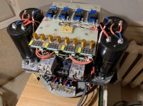
Don't underestimate the size of the caps
FWIW its a good idea to use an 800 degree silver solder on the tube connections!
Last edited:
Yeah, I'm going to change those 8 caps in the PSU to some fewer and bigger ones, maybe 1-1 or at most 2-2 of them. Diode bridge individual diodes also strengthened to 15A types (and even faster-recovery types than original ones). I hope you meant something like this and I understood you correctly.
(Uh, that DSD-modulated RF tube thing must be killer.. DSD.. tubes.. lol. Amazing).
Last time I used 10% silver containing solder from Mundorf. I think that will do the trick here too. Using 4 new septar sockets with gold contacts, we'll see.
(Uh, that DSD-modulated RF tube thing must be killer.. DSD.. tubes.. lol. Amazing).
Last time I used 10% silver containing solder from Mundorf. I think that will do the trick here too. Using 4 new septar sockets with gold contacts, we'll see.
Last edited:
Yeah, I'm going to change those 8 caps in the PSU to some fewer and bigger ones, maybe 1-1 or at most 2-2 of them. Diode bridge individual diodes also strengthened to 15A types (and even faster-recovery types than original ones). I hope you meant something like this and I understood you correctly.
(Uh, that DSD-modulated RF tube thing must be killer.. DSD.. tubes.. lol. Amazing).
Last time I used 10% silver containing solder from Mundorf. I think that will do the trick here too. Using 4 new septar sockets with gold contacts, we'll see.
The physical sizes looking at some of the example builds, with a slow start. I made it difficult on myself to try to limit inrush to 4-5A.
On the DSD, yep I think it's going to be a long burn project. If LTSpice is to be believed at least 16-20 tubes per channel which is why I suspect I may never finish it or compromise accordingly. But you've gotta have a moonshot project right?
I want to know if VintageFart's key in the amp is to prevent it being opened or being used without permission
or being used without permission
Btw, do I really need a 600VA transformer for the amplifier circuit itself ?
Looking at the PSU schematics and the parts list, Tim Mellow specifies a 625VA transformer for T3. Whereas I think a 250VA (toroidal) would be already okay. Am I wrong or was the author just over-spec'ing it for a 'hi-fi' reason ? (We like everything oversized, except THD, IMD and noise)
So what is REALLY needed here for T3 ? (For average 8 Ohm speakers).
https://www.diyaudio.com/forums/tub...signed-tim-mellow-4-6c33c-27.html#post2504540
I suspect there's a lot of current from T3 being taken for the -435V rail through the doubler from the 120V transformer.
I suspect there's a lot of current from T3 being taken for the -435V rail through the doubler from the 120V transformer.
And a last, maybe crazy question: since this is a Class-A push-pull amplifier.. would it be possible IN THEORY to somewhat reconfigure it so it becomes a strong Class AB, still retaining all the reliability and OTL sound of the original design ?
Well, it will be in Class A only for the first 2 Watt or so. If you increase the volume it will eventually enter class B. Remember, Tim biased the outputs at 200mA, once these 200 mA are used up one of the tubes will cut off, while the other tube can be pushed to 2A.
RV3 allows you to adjust the quiescent current through the output tubes up to 400mA (thats the max 60W per tube) or down to near zero if you wish. So you can choose within these limits when the amp is going to leave class A.
https://www.diyaudio.com/forums/tub...signed-tim-mellow-4-6c33c-27.html#post2504540
I suspect there's a lot of current from T3 being taken for the -435V rail through the doubler from the 120V transformer.
Ah, no ... there's about 5mA per channel drawn from the -435v rail.
250VA is about the smallest size for T3, if you never bias the outputs higher than 200mA and you never do things like sine testing into a dummy load. The crest factor of a musical programme is your friend.
Also have in mind that the tubes produce a lot of heat so the trafo has to have thermal margins depending on how much heat is transferred from the tubes in your build and whether it is free standing or bured inside the chassis.
Yeah, I'm going to change those 8 caps in the PSU to some fewer and bigger ones, maybe 1-1 or at most 2-2 of them. Diode bridge individual diodes also strengthened to 15A types (and even faster-recovery types than original ones). I hope you meant something like this and I understood you correctly.
(Uh, that DSD-modulated RF tube thing must be killer.. DSD.. tubes.. lol. Amazing).
Last time I used 10% silver containing solder from Mundorf. I think that will do the trick here too. Using 4 new septar sockets with gold contacts, we'll see.
I would stay away from the gold contacts- the socket will fail after a certain amount of time (often the 6C33 lasts longer than the socket) and the gold will not affect that.
There's no point in silver solder if the component leads do not also have either silver or gold plating. If they are tin-plate, use SN63 (which is a eutectic solder); that will give you a lower noise solderjoint. Only use silver bearing solder if silver or gold is going to be soldered.
Well, it will be in Class A only for the first 2 Watt or so. If you increase the volume it will eventually enter class B. Remember, Tim biased the outputs at 200mA, once these 200 mA are used up one of the tubes will cut off, while the other tube can be pushed to 2A.
RV3 allows you to adjust the quiescent current through the output tubes up to 400mA (thats the max 60W per tube) or down to near zero if you wish. So you can choose within these limits when the amp is going to leave class A.
Hmm interesting. Tim said in the article it's a class A amp:
If you can increase the load to between 40 and 100Ω, then you can easily obtain 50W of pure class A power.
Pure class A at 50W ?
The physical sizes looking at some of the example builds, with a slow start. I made it difficult on myself to try to limit inrush to 4-5A.
On the DSD, yep I think it's going to be a long burn project. If LTSpice is to be believed at least 16-20 tubes per channel which is why I suspect I may never finish it or compromise accordingly. But you've gotta have a moonshot project right?
I want to know if VintageFart's key in the amp is to prevent it being opened or being used without permission
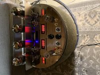
Hi NickKUK! The key is just a regular ON/OFF switch but could also be used as a PFWA (Protection From Wife Action). Just remove the key to activate this function
(I have 4 tubes, all good, same batch - hope the best).
Hi Vortex! Glad to hear you are on the way! What I recommend you is to cook and select the power tubes before using them. I made a simple supply for plate +150V (able to provide at least 03-0,5A&150V) and second one for grid -70V, no power needed - couple of mA is enough. Connect a 0,1ohm resistor in plate line and any suitable mV meter across it to read the current flowing through the plate. Into the grid provide the voltage from -70V source over the (for example 10-20kOhm) pot - so you can adjust the grid bias - and also Vmeter in between grid and cathode to read the grid voltage. Adjust the Ia to 100mA in the
beginning and let the tube warm. After 15-30 min the current will raise to 150-200mA, if more - decrease the bias (increase the grid voltage). Let the tube run for couple of hours and follow the Ia. It will finally stabilize and normally even drop down a bit after couple of hours running. The tube has reached the thermal stability at that point and you can write down the grid voltage value for it.
The tricky part of that is the fact you have only four tubes! You have to choose tubes for one channel with grid voltages close to each other as possible. The grid voltage swing for 6C33 &200mA could vary from 40V to 60V and allowed difference for the channel I recommend to stay in 2-3V. So, you have to find two pairs from four tubes. If the grid voltage is below 40V or over 60V I do not recommend to use these as they will act "nervously", out of specs.
Anyway, wish you luck! And by the way - the amp is sounding amazingly good!

I strongly recommend that if you are using NOS tubes, before putting any plate voltage on them at all, run the filament circuits for 3 days and nights. This preconditioning can double the lifetime of the tube. This applies to most power tubes, not just the 6C33. Some tubes, like the Chinese 6N13, need 4 days and nights of preconditioning.
ARES_V4 - Aresaudio
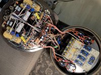
Qui il mio prototipo con 4+4 tubi finali con pcb che comprende tutti gli stadi, alimentazione, drivers, soft start e protezioni
Thi is my prototipe of 4+4 power tubes on pcb with power supply, drivers, soft start and Protections sections on board.
Qui il mio prototipo con 4+4 tubi finali con pcb che comprende tutti gli stadi, alimentazione, drivers, soft start e protezioni
Thi is my prototipe of 4+4 power tubes on pcb with power supply, drivers, soft start and Protections sections on board.
Last edited:

Ciao francolok, questo è un forum di lingua inglese. Se desideri postare in un'altra lingua ti viene chiesto di postare anche una traduzione. Grazie.
Google Translate:
Hello francolok, This is an English speaking forum. If you wish to post in another language you are asked to post a translation as well. Thank you.
- Home
- Amplifiers
- Tubes / Valves
- OTL designed by Tim Mellow with 4 6C33C?