This is all about how far you want to push it. I take it you are set on a certain chassis; am I right?
I design my own chassis, but its dimensions is ideal now, so I just ask how can I improve the power supply if I use one for both channels. Maybe is possible to put two rectifiers with all capacitors, but I am afraid that it will take a lot of time to design it and also a lot of money to let it manufacture - I would like to shield audio path from PSU part by steel partitions.
Another possibility is to use the original Mellows schematic with serial connection of filtering capacitors (they may be smaller then), but simulation shows that it does not have a good filtering effect - 7Vp-p ripple at high current consumption. Someone posts that it is OK, but i dont feel good about it ...
Another possibility is to use the original Mellows schematic with serial connection of filtering capacitors (they may be smaller then), but simulation shows that it does not have a good filtering effect - 7Vp-p ripple at high current consumption. Someone posts that it is OK, but i dont feel good about it ...
Hi!
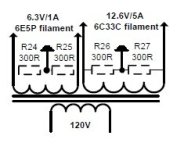
Can anyone tell me how to connect the heating in series on the 6C33CB tubes? Which is the best solution? Which pins to connect?
Can anyone tell me how to connect the heating in series on the 6C33CB tubes? Which is the best solution? Which pins to connect?
Tyimo, Better connect the 2 heater filaments in serie... but be aware those tubes are current hungry for the first 5 seconds, it's huge I did a compound regulator to limit the current first then the tension at the end... The wiring is in the picture...
and Datasheet
and Datasheet
Attachments
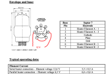
Yes Tyimo, it's grounded in the middle on the design... It's a best practice to power up the channel.... wait for the temp to stabilize, and then measure the voltage between the mid point of the heaters of the tube to ground...after that you can decide to ground or adjust the level of the mid point to a negative PSU...
After some months (quite some.. 2+ years actually) .. continuing the project, waiting for a bunch of parts from Mouser 🙂
Digging myself into the programming of the microcontroller meanwhile. 😎
This is the "smaller" heater transformer for the 4x 6S33S-V tubes, the 2 anode PSU toroids waiting on the floor to be built in.
Tough work is expected with the soldering iron even with all transformers taken out of the chassis.. fiddling around the input tube pins uh, .. but progressing, progressing. (Input tubes will be covered by the socket's metal cover for even more shielding).
Forced air cooling not planned yet, I had cut plenty of holes on the front-bottom and on the back-top plates for an adequate airflow, assuming hot air is moving upwards so cold air intake will function as intended when the tubes generate this slow airflow. We'll see how strong it will be at all, on spring-winter-autumn room temperature. If not enough, I'm ready to make a cutout on the top panel and place a big silent fan onto the top.
Tubes all Soviet.. still 6N2P-ER (extra longlife) on the inputs, Winged-C 6J32P as drivers and of course the pair-matched 6S33S-V-s.
Going with DC heating for the small tubes, left on AC for the big ones.
The worst part is waiting for parts, each week some tiny thing is missing 😆 but hey, I don't want to buy everything in bulk just because one project..😏
Oh, 2 big long sturdy anodized aluminum heatsinks are coming onto the 2 side panels too so the Hexfreds will be mounted onto the wall inside.
This is where I am with my love project for now.
I hope I gain some speed now because I have the time for it. Some hectic 2 years behind me ...
...

Digging myself into the programming of the microcontroller meanwhile. 😎
This is the "smaller" heater transformer for the 4x 6S33S-V tubes, the 2 anode PSU toroids waiting on the floor to be built in.
Tough work is expected with the soldering iron even with all transformers taken out of the chassis.. fiddling around the input tube pins uh, .. but progressing, progressing. (Input tubes will be covered by the socket's metal cover for even more shielding).
- All inputs fixed, no pot - adjusting volume on the DAC.
- RCA-s get 50k instead of 100k for the beginning (2x100k || precision resistors) to further lower input sensitivity but I might turn back to 100k as in the original design, we'll see.
- Neutrik XLR inputs beneath the input tubes, 25k (2x50k || precision resistors) for the same reason / signal.
- Feedback (R3) and everything else left on original value.
- Input caps decreased from 1uF to 470uF, still providing a great low-end response (RCA - 6.7 Hz, XLR - 13.5 Hz... original value gives ~2 Hz high-pass filter, no need to go that low I think and I might save some space because the input is really crowded in my build).
- N1 and N2 swapped to Zener diodes (2 together for each, limiting voltage as intended in the original design).
- Ditched C8-C15 and corresponding resistors (R23-R30), using 2x 2200uF modern low-ESR 105°C electrolytics (per side) with quality film on top of them as usual.
- White OLED screen via SPI interface, NodeMCU ESP8266 being programmed. Wifi also available, amplifier control via HTTP first, then via Android app (add +1 year) 😏
- SSR control via the ESP, delayed start for each transformer so no inrush current limiter needed (25+250+400+400VA) and proper startup sequence fully implemented.
- Realtime Clock with full calendar and flash (good 'til 2100) on the ESP with a user-replacable CR2032, time & date will be set either manually or via NTP if wifi and internet is ON, I'll program it into the menu to be selectable.
- A bunch of DS18B20+ is coming too, to monitor internal heat at different points (ambient air around caps, trafos, 6S33S sockets).
- Manufacturer-stated lifetime of caps will be monitored, different value for each kind so as time passes the amp can warn the owner to replace certain caps with new ones, including resetting the counter for replaced ones to zero and adjusting lifetime hours if needed / different kind.
- Some foolproof emergency measures will also be implemented, e.g. full control of ON/OFF procedure. Especially if the amp goes off (due to power outage in the home or for whatever reason), the microcontroller will have enough reserves from it's own big caps (for about 1.5-2 secs) to write quickly (within milliseconds) the last "elapsed time" counter data (for the caps) into the flash memory and also to log an unclean shutdown here, so when power is back and the controller starts again (standby mode), it won't allow the user to switch back the amp for about 10-15 minutes (or depending on cap voltage, we'll see), so pressing the front button will do nothing except navigating in the menus.
Forced air cooling not planned yet, I had cut plenty of holes on the front-bottom and on the back-top plates for an adequate airflow, assuming hot air is moving upwards so cold air intake will function as intended when the tubes generate this slow airflow. We'll see how strong it will be at all, on spring-winter-autumn room temperature. If not enough, I'm ready to make a cutout on the top panel and place a big silent fan onto the top.
Tubes all Soviet.. still 6N2P-ER (extra longlife) on the inputs, Winged-C 6J32P as drivers and of course the pair-matched 6S33S-V-s.
Going with DC heating for the small tubes, left on AC for the big ones.
The worst part is waiting for parts, each week some tiny thing is missing 😆 but hey, I don't want to buy everything in bulk just because one project..😏
Oh, 2 big long sturdy anodized aluminum heatsinks are coming onto the 2 side panels too so the Hexfreds will be mounted onto the wall inside.
This is where I am with my love project for now.
I hope I gain some speed now because I have the time for it. Some hectic 2 years behind me
...
Hi all. After a couple years in storage, I decided to pull this project off the shelf. I remember there were tweaks to the original Tim Mellow design. I have a lot of the parts and a fancy-shamansy chassis all ready.
So, which schematic should I look too?
So, which schematic should I look too?
Here is the chassis I built. All the power supplies and can caps will go on the bottom and the 6C33C tubes will line up across the top tier.

Here are two tube sockets and I have two more that I can’t find that are unusual but difficult too.


Good decision.Hi all. After a couple years in storage, I decided to pull this project off the shelf. I remember there were tweaks to the original Tim Mellow design. I have a lot of the parts and a fancy-shamansy chassis all ready.
So, which schematic should I look too?
Take this one - the original one. 😏
Note 1: this is 1 psu for both sides while only 1 amp circuit is shown (obviously).
Note 2: typo on the PSU part, C8-C9-C8-C9 -> C8-C9-C10-C11. (I replaced them btw with one big cap in each +/- rail).
- Home
- Amplifiers
- Tubes / Valves
- OTL designed by Tim Mellow with 4 6C33C?