The measurements I posted are an average of the left and right channel
Driver tube average between the left and right first number from wiper to pin 3 21K, wiper to pin 1 42K.
Output tube average between left and right wiper to pin 3 29K, wiper to pin 1 42K.
spiggs,
Got it! Very helpful. Thanks!
Regarding the motor run cap question - I plan to wire in a 60uF DC-Link type film cap paralel to C2, because I have it and can do it under the top plate. YMMV, but a lot of builders seem to think an oil or film cap in the last position of the supply provides for a better sounding amp.
I think an SE amp needs a power supply as quiet as one can get it and the 120uF final cap specified seems on the low side for an SE amp drawing ~200ma from the common supply. I ordered a 390 uF for my C2 when Mouser was out of stock for the 120uF George specified. My choke is a 10H.
...YMMV, but a lot of builders seem to think an oil or film cap in the last position of the supply provides for a better sounding amp.
...My choke is a 10H.
I have a 6H choke in mine. Just wired in a 100UF motor run cap and gave it a listen. Certainly does not seem to degrade the performance so I will keep it in and do some more listening.
I plan to wire in a 60uF DC-Link type film cap paralel to C2, because I have it and can do it under the top plate. YMMV, but a lot of builders seem to think an oil or film cap in the last position of the supply provides for a better sounding amp.
I think an SE amp needs a power supply as quiet as one can get it and the 120uF final cap specified seems on the low side for an SE amp drawing ~200ma from the common supply.
First off I must clarify some things about caps for motor use because people still get this wrong, which can lead to poor results including exploded or vented caps.
A motor START cap is an electrolytic based part. It is NOT designed for continuous use, and characteristics are lousy. These are switched on to get a small motor spinning, then disconnected during motor operation. It may (and has) vent it's electrolytic goo all over the insides of your new amp when continuously connected to power. Some EBAY vendors have been selling these as RUN caps, either by stupidity or with fraudulent intent.
A motor RUN cap is almost always polypropylene based film (some really old ones are PIO) and are continuously connected to the AC power line during use. A considerable AC current (AMPS!) must flow through this cap whenever the motor is on. It must be built to withstand every transient on that AC line. These have the low ESR and ESL characteristics that allow them to deliver fast pulses of high current needed when a big bass drum hit tries to instantaneously reverse a large woofer's cone travel.
Adding such a cap makes a big difference in a class AB amp where the power supply current varies over a large range. SSE and TSE users have reported improved dynamics in their amps for 15+ years from adding such a cap.
Experiments conducted nearly 20 years ago when I had access to an HP component analyzer proved that an electrolytic and a poly film cap complemented each other providing a lower ESR and ESL than the same capacitance value from either kind of cap individually. The test ran from 10 Hz to 1 MHz. This was some time ago, and capacitors have generally improved over time, so the results may be different today.
There have been at least two Tubelab amps made by forum members that used NO electrolytics in their build. All capacitors were film caps, many off board. Extreme? It's all up to the builder as to what's extreme.
I have used such a cap in every amp I have built. Most are 100 uF ASC 370 VAC motor run caps because I got a box full for $10 each over 10 years ago. I have used other poly film caps in places where these big air conditioner caps don't fit.
There has been some speculation as to just how many DC volts a 370 VAC rated cap can eat. 370 * 1.41 is 522 volts so you should be safe at 500 volts, many users have gone a bit further including myself, but I would use a 440 VAC cap in a 600 volt build. I have some specialty caps for such a build though.
My TSE has a 40 uF DC link cap in it because it's the biggest cap I could get under the deck. It uses 45 tubes and the total power supply draw is only about 85 mA.
Yes, in an amp drawing 200+ mA I would put the on board cap and the supplemental cap total in the 300 uF range.
Unfortunately the availability of 300+ uF caps that eat 500 volts and fit in the existing PC board is very limited......I find a total of zero.
Last edited:
The motor run cap I have is 100uF and rated at 450VAC. What I have found is the 100uF size in that rating can be found with a bit of searching for under $15. Based on a target of around 300uF total I think I will try a second one in parallel plus the onboard 120uF for a total of 320uF.
Yes, in an amp drawing 200+ mA I would put the on board cap and the supplemental cap total in the 300 uF range.
Unfortunately the availability of 300+ uF caps that eat 500 volts and fit in the existing PC board is very limited......I find a total of zero.
If anyone is interested I found this one at Mouser - ALA7DA391CF500 KEMET | Mouser
Hopefully there is nothing untoward with this part - I didn’t see a problem.
Last edited:
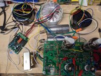
Pic of latest setup using 2 of the motor run caps and sounding good.
As a side note I have been trying to setup REW to use as a distortion measurement tool. In the instructions posted here on diyaudio it mentions using the output from a Focusrite Solo for the sign wave to the amp and using it's input hooked to the output of the amp for the measurement software. When I tried hooking it up to the UNSET it was a very unhappy amp.
As a side note I have been trying to setup REW to use as a distortion measurement tool. In the instructions posted here on diyaudio it mentions using the output from a Focusrite Solo for the sign wave to the amp and using it's input hooked to the output of the amp for the measurement software. When I tried hooking it up to the UNSET it was a very unhappy amp.
Attachments
I decided to try some different driver tubes and replaced the 6J51Ps with a pair of 6KT6, a physically smaller tube but hopefully still up to the task. I plugged them in and let them cook for a bit at 70V plate voltage then brought them up to 125V and rechecked the bias at 80 mA for the output tubes.
First thing I noticed is they are much less microphonic than the 6J51P. Second setup like this with the 2 supplemental motor run caps with a total of 320uF of C2 the UNSET is sounding good with everything I throw at it. I was very much enjoying some punk rock with an aggressive rolling drum line, guitar, and screaming singer. After that some EDM followed by Blues and Soul.
First thing I noticed is they are much less microphonic than the 6J51P. Second setup like this with the 2 supplemental motor run caps with a total of 320uF of C2 the UNSET is sounding good with everything I throw at it. I was very much enjoying some punk rock with an aggressive rolling drum line, guitar, and screaming singer. After that some EDM followed by Blues and Soul.
@ George:
can this pmosfet be an alternative for the cathode driver?
https://www.mouser.it/datasheet/2/308/1/FQP2P40_D-2313879.pdf
Why is it rated at 0,5W/°C being a TO220?
Thank you in advance
Roberto
can this pmosfet be an alternative for the cathode driver?
https://www.mouser.it/datasheet/2/308/1/FQP2P40_D-2313879.pdf
Why is it rated at 0,5W/°C being a TO220?
Thank you in advance
Roberto
I have used those mosfets in low powered test amps. They work but can not be trusted without some serious testing. I have not tried these in anything bigger than a 20 WPC amp that ran on 320 volts. On Semi / Fairchild still does not acknowledge the secondary breakdown failure mechanism in mosfets.
If you look at the DC curve shown in their data sheet it is exactly equal to the static dissipation rating. A theoretical perfect part under ideal conditions MAY be able to achieve this. The next identical part from the same batch could fail under far less strenuous conditions. As others have found, these failures do not happen immediately. Often they are weeks to years later.
These devices are designed "to provide superior switching performance" and not for continuous operation in the linear region where they may fail. For something making big power that needs to work, I would prefer a fet rated for operation in the linear region, like a class AB audio amp, power supply, or DC load tester. Unfortunately these are rare and expensive today.
The 0. 5W/°C spec is from the case to the heat sink, again under ideal conditions (perfectly flat surfaces with a very thin layer of heat sink compound). The same part is rated at 1.98W/°C from the die to the case.
These add like electrical resistors in series, so from the die inside the package to your heat sink, you are looking at about 2.5W/°C PLUS any insulator used. Then you must consider how the heat sink gets the heat into the surrounding air, and this is a BIG variable. The curves given in heat sink data sheets are usually under best case conditions as well.
As a side note I have been trying to setup REW to use as a distortion measurement tool. In the instructions posted here on diyaudio it mentions using the output from a Focusrite Solo for the sign wave to the amp and using it's input hooked to the output of the amp for the measurement software. When I tried hooking it up to the UNSET it was a very unhappy amp.
Good to hear you are enjoying the sound from your UNSET.
This observation about its behavior under REW testing is a bit “unsettling”! Any theory about the cause of this? Has the same testing set-up produced good results on other amps you built/tested?
This is the first time I have used REW for testing and I have not worked all the bugs out yet As detailed in the instructions in the first post of the REW thread I fed the output of the UNSET to the Solo using a load resistor and voltage divider. Then I fed a 1khz sine wave from the Solo's output to the input of the UNSET. Doing so I believe caused the input and outut to couple and the amp to oscillate as George has warned about....This observation about its behavior under REW testing is a bit “unsettling”! Any theory about the cause of this? Has the same testing set-up produced good results on other amps you built/tested?
The solution was to use a seperate device for generating the sine wave by just playing a 1khz test file through the chromecast music device I have been using to play music for testing. The amp is perfectly stable this way.
I still don't have any good readings from the UNSET or any other amp I tried and am still trying to figure REW out.
For the final packaging in a case I am still undecided if I should try and route the inputs to the back panel a few inches away from the outputs or if I should keep them on the front to minimize any chance of issues. I have also thought about using transformers to add a balanced input although I don't know if this will help or hurt.
Good luck with your REW exploration. That is a journey I still have to make.
Regarding routing the inputs, my personal preference is not to have interconnect wires dangling over hot tubes to reach inputs on the front of the amp. I never had trouble placing my RCA connectors at the back, with shielded wire going to the inputs on the PCB, the wire placed snug in the corners; but good wire is needed. (Makes no sense to pay a lot for fancy interconnect wire if one has “cheap” wire the last 12”).
Yes, a template for the top plate cutting would be great. I have not started soldering yet, so I have planned to make a photocopy of the PCB for my own template use. Hopefully it scales correctly. If necessary, I could put one in the post for you (not sure how to preserve scale otherwise in electronic form).
...Regarding routing the inputs, my personal preference is not to have interconnect wires dangling over hot tubes to reach inputs on the front of the amp. I never had trouble placing my RCA connectors at the back, with shielded wire going to the inputs on the PCB, the wire placed snug in the corners; but good wire is needed. (Makes no sense to pay a lot for fancy interconnect wire if one has “cheap” wire the last 12”)...
I plan to use Mogami W2330 for the internal chassis wire to the inputs. If I run them to the front I would make a matching preamp that would sit below with the outputs on the front to avoid running long wires over the top. Undecided though, I may just make it an integrated amp like my SSE to keep things simple.
I realized today that the choke I am using is rated for 200mA. It is the Triad C-14x. With the output tubes biased at 80mA that puts me at 160mA plus whatever is going across the input tubes. Should I be looking for something that can handle more current?
I would be surprised if you are drawing more than 40ma for the front tubes and exceeding your 200 ma choke capacity. It would be easy enough to check the current requirements for the two driver sections by measuring voltage across R7 and calculate.
Let us know if you check - it would be useful info to have. I was planning to use a 220ma choke.
Let us know if you check - it would be useful info to have. I was planning to use a 220ma choke.
- Home
- More Vendors...
- Tubelab
- UNSET Beta Board Build