I forgot to answer to this point: the reason why I asked is that 99.99% of the commercial amps are based on expensive 12AX7, and that mod could be applied to commercial amps by substituing the RC on the cathode with this system.I have not tried to pentodify a triode since I see no reason to do so.
@Tubelab_com
I will give this circuit a try, reducing R5 until it is stable on the whole range of U2.
U2 will be a log pot, R5 will be most probably switchable to have two different loadlines.
Let's see if the voltage drop on plate voltage due to the current drawn by g2 during peaks will be euphonic.

I will give this circuit a try, reducing R5 until it is stable on the whole range of U2.
U2 will be a log pot, R5 will be most probably switchable to have two different loadlines.
Let's see if the voltage drop on plate voltage due to the current drawn by g2 during peaks will be euphonic.
Almost two decades ago this certain combination of transformers and tubes caused bit of buzz on this forum:
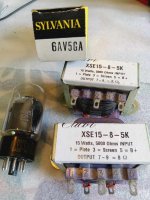
There's a thread about it somewhere but the important information is summarized on the Tubelab page here: http://tubelab.com/articles/tube-testing/6av5-sweep-tube/
I remember building two different amps using the same OPT/tube combo but none of them was 100% successful, the first one had a too small power transformer to bring the best out of the tubes and the second one had a hum problem that I never managed to fix completely.
When I saw a pair of the Edcors for sale locally the other day I got a bit nostalgic and couldn't resist buying them. I also still have about a dozen Sylvania 6AV5GAs left on the shelf.
I've been thinking about trying the UNSET topology for a while, perhaps these tubes and transformers would be a good place to start?
Last edited:
I should still have those OPT's in a box somewhere, and I know that I have some 6AV5's in my storage shed. I have a new really "out there" driver circuit that shows good performance in bench testing, but hasn't been heard through real speakers yet, so I'll see if I can find the OPT's and maybe wire something up.
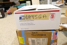
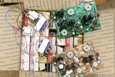
Some digging through boxes has uncovered all of the necessary ingredients for this recipe. One UNSET board is the original prototype, probably untouched since I made a commercial PC board. The other UNSET board has been the subject of several experiments, and is not in original condition. I should have another populated board or two, but I can't find them. In a random stroke of luck I found a box labled "Small Transformers" that had not been opened since I left Florida 10 years ago. It contained the old Edcors, apair of even smaller "Fender Champ OPT replacements" that I had long ago forgotten. A box labeled 6AV5GA contained 45 tubes of various flavors.
I envision two experiments depending on how things go. The first experiment will use one of the UNSET boards configured for the 6AV5GA and possibly for a bigger tube or two for baselines. I have the Edcors, and a few other OPT's to test.
The driver circuit on the UNSET board can't quite make enough gain to drive a big tube like the 6LW6 to clipping from a low output source like an iPhone (yes, people do this). Here I will test a one channel prototype driver circuit that has been shown to be capable of stupid amounts of gain, since my original thinking revolved around a guitar amp. The Octal Unset Output Board will be used for these tests with bench power supplies capable of up to 650 volts.
The original thread where the 6AV5 met the Edcor OPT's is here:
https://www.diyaudio.com/community/threads/the-edcor-meets-the-6av5.74650/
After nearly 20 years, it's time to try some new tricks....and some old ones. These experiments will probably get posted in the Tubes / Valves forum for a larger audience, but I will link to it here.
Attachments
Very interesting! I'm guessing CCS/mu-follower loaded pentode or perhaps even a FET gain stage?capable of stupid amounts of gain,
The circuit started out as a breadboard configured like the saturator stage that I used as the input stage in a guitar amp. It was called the Saturator since it could be driven to saturation directly from an electric guitar with its volume set to 1 out of 10. The saturator was essentially a pentode gain stage with its plate load resistor bootstrapped to provide a nearly infinite load impedance. Then I applied an UNSET topology to the grid and cathode causing a reduction in gain and THD. Next, I put a pot and a cap in series from grid to ground to act as a variable shunt for the AC feedback to allow for variable gain. The circuit looks a lot like what Zintolo shows in post #562.
It can be seen in post # 110-114 and 119 here:
https://www.diyaudio.com/community/...he-way-i-always-wanted-to-do-it.410333/page-6
And in post #173 here:
https://www.diyaudio.com/community/threads/tubelab-wants-a-new-guitar-amp.408097/page-9
In that thread the unique driver and the UNSET output board were paired and created a very useful guitar amp. I did not do much other testing before tearing the entire setup down for some high power P-P testing. I plan to go back to this point
That’s nice! I’m very curious as a clean yet high-Zout power amp is what I’m working on.
Do you bootstrap splitting the saturator load in two and connecting the middle point to the output tube’s pmosfet source through a capacitor?
I did it with real triodes as drivers and works fine for Hi-Fi.
For guitar amps I’d bootstrap through a voltage divider from the anode of the output tube to the same middle-point of driver’s load.
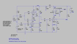
The driver tube circuit is almost identical to what you drew in post #562 except that the screen grid has its own divider so the voltage on the left end of R5 does not change with tube or G2 current. Most if not all of the component values are different and chosen by the "Guess, try it and see what happens, and if it doesn't work, guess again" method. I have been playing with tube stuff long enough that my guesses are usually close enough for the circuit to work.
Since the plate load, R1 has nearly the same AC voltage on each end, it looks pretty big to the tube.
Since the plate load, R1 has nearly the same AC voltage on each end, it looks pretty big to the tube.
Interesting! Assuming that the mosfet on top can be replaced with a triode, this circuit could be a way to put 6BL8 and similar triode/pentode compactrons to good use. Their 300mA heater equivalents are cheap and have better heater-cathode insulation.
Is it important for the stability of the unset even in “guitar-mode”?the screen grid has its own divider so the voltage on the left end of R5 does not change with tube or G2 current.
The apparent load impedance seen by the active tube depends on how accurately the follower copies what's on the plate and puts it on top of the load resistor, and the value of R5 and the divider that feeds it. The Gm of the follower device is the most important spec for accurate "following." In this aspect, a mosfet is hard to beat. I have been gathering parts and doing a few simulations for a guitar amp I will call MetallicAmp, all tube, no glass. Here I will use only metal cased vacuum tubes and other parts that were available before WWII. I have a simulation that uses a pair of 6SJ7 pentodes driving a 6V6. Both of these tubes were made in metal and glass envelope versions as was the 6L6. The Saturator gain is about 800 in this case. That is approaching the level where tube microphonics becomes an issue. Note that this is a simulation only I have not built this yet. I have built several mosfet loaded saturators. and one with UNSET features called the UNSETURATOR breadboardInteresting! Assuming that the mosfet on top can be replaced with a triode, this circuit could be a way to put 6BL8 and similar triode/pentode compactrons to good use. Their 300mA heater equivalents are cheap and have better heater-cathode insulation.
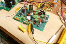
I desire a guitar amp that can be adjusted to play very cleanly and also be capable of a "full metal racket." The saturator allows this by using a 2 meg pot in place of R5. For minimum distortion the screen grid and plate voltages need to be stabilized. The UNSETURATOR board seen here has a pot in place of R5 and a pot for U2 and some trimpots to adjust other voltages for different tube types. There are two tube sockets wired in parallel so I can test 7 pin and 9 pin tubes. This board can get a voltage gain approaching 1000 with some distortion, but it can also get a gain of 60 while putting out 50 Vrms at 0.136% THD with the right tube! Most of the tubes that I tried got 0.2 to 0.4% THD at that level.Is it important for the stability of the unset even in “guitar-mode”?
Attachments
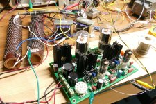
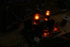
OK, It took a bit of digging and soldering but overall this was an easy test with minimal effort. I dug up an old UNSET board, rewired the jumpers to suit a pair of 6AV5's, plugged in the first pair of Sylvanias that I found that looked the same internally, flipped the switch and both channels sprang to life with nearly equal performance. I set the power supply on 300 volts and the idle current at 65 mA per tube. This burns about 20 watts in each tube / mosfet pair. I let it cook at this level for about 20 minutes, then killed all the room light. Nothing is glowing except the heaters and cathodes.
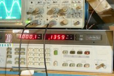
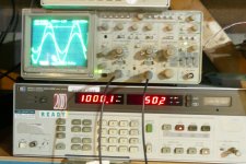
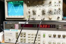
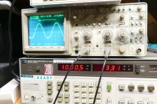
Preliminary testing on the 6AV5 / Edcor combination in an UNSET board shows good performance at 1KHz with the onset of clipping at just over 6 watts output and 3.42% THD at 7 watts. reducing the frequency to 100 Hz gives 3.4% THD at 5 watts. Saturation is evident at power levels above 2 watts at 40 Hz. I have not tried any cathode feedback yet, nor have I tried to UL wire an UNSET board. These may take a day or two to get to. The power supply was set to 300 volts and the idle current was 65 mA per tube. Both channels are shown on the scope screen at the same time. They are nearly identical except a slight difference at the bottom.
I'll hook up some music and speakers the next time I am the only one home.
Attachments
Can it be R11? So it changes the load seen by the unset?The saturator allows this by using a 2 meg pot in place of R5.
I’ve bought some cheap 6J5P for these kind of tests in guitarland, but on LTSpice they seem very good for Hi-Fi as well, being linear and with good amount of gain.This board can get a voltage gain approaching 1000 with some distortion, but it can also get a gain of 60 while putting out 50 Vrms at 0.136% THD with the right tube!
I did simulate and then tried at 40%, 23% and 0% UL (aka pentode) with some standard audio tube (should be KT88 IIRC): I preferred the pentode the most and the 40% the least.nor have I tried to UL wire an UNSET board
It’s a pity because supplying g2 through OPT taps is always intriguing for its simplicity.
Yes, R11 in my schematic, and R5 in yours.Can it be R11? So it changes the load seen by the unset?
In the thread from 18 years ago I tested some 6AV5 tubes in UL on a relatively low B+ voltage. The max spec is somewhere around 200 volts but the older design sweep tubes were more tolerant of excess G2 voltage. I will eventually get time to find their melting point.
Right now, I need to build a PC for one of my grandkid's birthday, so the tubes got pushed off the workbench.
If it is a high-performance pc, you could install HQPlayer on it and explore upsampling. It deserves to be heard. Otherwise with lower performances pc you can install Daphile on a usb-pen. It is a very very good music player and can upsample as well.
The scratchy and simplified UNSETURATOR is what I want to try as a preamp stage for the guitar amp I was talking about in another thread: a PP with 40% UL to linearize the output tubes, and a differential-shade-positive-feeeback to run the LTPI with CCS-like plate loads (and a real CCS on the joined cathodes): a power amp superclean even when loud, with the speaker quite free to move, and the “UNSETURATOR” preamp stage to set the distortion characteristic of the amp.
I think I speak for many of us when I say that your efforts are very much appreciated. Thanks! It's very educational for all of us that you have the gear, the skills and the nerves it takes to test all these tubes and circuits.OK, It took a bit of digging and soldering but overall this was an easy test with minimal effort.
- Home
- More Vendors...
- Tubelab
- UNSET Beta Board Build
