George.. Your not into the spirit i remember.. I would like to see the paint blistering on those metal can 6l6's
I have tried 6L6 types, 6V6 types (old GT's and metal) KT88's, but haven't got to EL34's. All seem to make about the same power as the same tube did when triode wired in the usual manner. I tried 6W6GT's which were originally created for TV vertical sweep. Unlike a horizontal sweep (line output) tube which runs in basically a switched current source mode, the vertical sweep tube is run as a class A SE amp that is optimized for 50 or 60 Hz depending on where you live. I exploited this fact early in my youth by ripping the entire vertical sweep section out of some junk TV sets including the OPT and connecting it between an electric guitar and a speaker.Hi George, which usual audio tubes have you tested, and why do you think they have this limited amount of power?
The UNSET board drives the output tube through the cathode, applies negative feedback through the control grid, and fixes the screen grid at constant voltage. This provides triode like curves from pentode like configuration. It offers triode like performance from TV sweep tubes on high plate voltages that would fail if run with G2 tied to the plate, due to low maximum G2 voltages. The screen grid in these tubes is much more sensitive than the screen in a typical audio tube. There have been some threads dating back over 10 years where several experimenters here tried different methods of driving both G1 and G2 at the same time since it was discovered that the typical audio tubes can not be driven to full power through the screen grid alone.
The majority of the drive voltage in the UNSET configuration is applied between the cathode and G2. The drive that is applied to the cathode is reduced by the negative (directly from the plate) feedback applied to G1. It is this feedback ratio that determines the slope and characteristics of the triode curves provided by the pentode - mosfet pair.
"George.. Your not into the spirit i remember.. I would like to see the paint blistering on those metal can 6l6's"
I went to a technical high school back in 1967-1970 where I was enrolled in a three year vocational electronics program. A local Air Force Base had donated a bunch of "obsolete electronics" to our school including a bunch of those metal 6L6 tubes still new in the RCA boxes. I blew up a lot of them in the quest for the loudest guitar amp in the school.
The teacher was somewhat interested in my ability to melt stuff back then so he bet me that I could not make a metal tube glow red. I got the plate up to about 40 watts of dissipation which should have made it hot enough to emit electrons, then hooked a couple of 400 volt Eico power supplies in series and applied that voltage between the plate and the outer metal shell. There was lots of smoke, stink, peeling paint and burning plastic on the base, but the vacuum failed before glow appeared.
I have no problem melting tubes that were free, I have too many of, or I will never use. These cost me about $15 each on Ebay so I will be nice to them.

Thanks George!
That is surprising to me, because in the simulations I did, EL34 and KT88 performed very well (the latter with 20% a-g1 feedback instead of 10%) both in terms of power, THD and DF: with a B+ of 460V and screens at 250V on a load of 3k, a-g1 feedback set to 150k+150k to 68k (the bottom mosfet dissipates 10W), 2nd and 3rd harmonics paired at around 24 Wrms.
Then I built two pairs of fullrange speakers (that still need painting) and I stopped collecting materials to put those simulations in reality.
Then there will be a subwoofer to be repaired and some other works at home between me and a GU50 UNSET.
Just thought I would bump this thread back up as a reminder to those who have not yet given their UNSET Beta Board build a go. I really like my 26HU5 build. It has proven stable and makes great music hooked up to any of my speakers, it's a keeper. I listen to it just about everyday although admittedly it is still without a case. I have started cutting panels but other distractions keep popping up. Most recently a couple of old motorcycles. So the UNSET has been providing the music awaiting it's case while I give other projects attention. I also have some solid state front ends waiting in the queue to hookup to an UNSET output section to see what that will do. But first a case for the 26HU5 build so I can get it safely into my main system.
Yep, the 12gn7a has been my driver tube of choice with the 26HU5 ouput tube. That gets me over 20 watts output with the harmonic profile I want all the way to clipping.
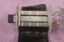
Getting unSET #2 ready with its older brother in the background.

Fired up and making music.

No rectifier tube, nor the FET g2 supply. Instead a tube voltage reg for the output screens.
The old Tek power tranny delivers a healthy 660V to the output plates, 360V goes to the 12HG7a's and g2 reg.
At the moment running with E130L and planning to try 6CD6GA, 8068 and 12E1. There are sockets wired up for EL509 as well.
It's too big to put in the rack and with the topcaps I want it behind a door or a cage. But that's a problem for later: first I need to clean up my workbench to do some measurements and figure out what is the best setup for this amp.
Fired up and making music.
No rectifier tube, nor the FET g2 supply. Instead a tube voltage reg for the output screens.
The old Tek power tranny delivers a healthy 660V to the output plates, 360V goes to the 12HG7a's and g2 reg.
At the moment running with E130L and planning to try 6CD6GA, 8068 and 12E1. There are sockets wired up for EL509 as well.
It's too big to put in the rack and with the topcaps I want it behind a door or a cage. But that's a problem for later: first I need to clean up my workbench to do some measurements and figure out what is the best setup for this amp.
These posts about successful implementations of Unset topology amps are whetting my appetite!
My thinking is that the Unset PCBs are more like handing out a fishing rod than handing out a fish. What sort of work are you doing before you start work on a particular implementation? For instance, I have a quad of CV345/12E1 tubes too, so I am interested on how you shall work with that option.
It would be interesting to have some table of the different tubes that have been tried, voltages and output transformers. Or am I over thinking this?
My thinking is that the Unset PCBs are more like handing out a fishing rod than handing out a fish........It would be interesting to have some table of the different tubes that have been tried, voltages and output transformers. Or am I over thinking this?
Not overthinking, just asking those who fished in that hole before what bait to use.
I have random notes scattered all over the place, but my experiences with pretty much all sweep tubes are similar. They all work pretty good with 150 to 175 volts on G2. The limiting factors are peak cathode current capability and plate dissipation rating. Lowering the OPT impedance usually brings more power until you start to approach the peak cathode current rating. There will be a point where idle current VS plate dissipation limits the maximum plate voltage. The 8068 is an oddball since it is basically a 6CD6 with the wimpy cathode from a 6L6GC inside. It was meant for steady state current flow in a linear voltage regulator. They used to go for stupid money, but now most of those old Kepco power supplies have died and been robbed of their tubes. I have about 20 all pulled from dead supplies, tested and graded for bias voltage needed to flow 100 mA. I think I found 2 or three bad ones out of 24.
I have a box full of pulled E130L tubes somewhere, but never tried them in UNSET. I have never ventured near 600 volts with them either. 6CD6's and the other sweep tubes with similar plate dissipation will make well over 100 watts per pair in push pull. I am currently in the process of testing UNSET for use in guitar amp applications.
Hi George, this has been one of my thoughts too, in PP.I am currently in the process of testing UNSET for use in guitar amp applications.
I tried some positive feedback too, in order to lower the DF and be more compatible with guitarland.
I ended-up with a simpler solution using local feedback: negative to screens and positive to grids.
Is it the limit you were mentioning for standard audio tubes? I indeed used higher voltages and flatter loads for the EL34.The limiting factors are peak cathode current capability and plate dissipation rating.
There are still some unexplored areas of opportunity in the UNSET design that may work well for guitar amps. I have just begun to experiment.
Every tube from a simple voltage amp triode to a monster transmitting tube should have a maximum plate dissipation spec. No vacuum is perfect, and none of the materials used in the manufacture of a vacuum tube are completely pure. As the operating temperature of any tube is raised, several things begin to happen. The concern with typical audio, radio, and TV tubes, often called receiving tubes, is the release of some of these impurities into the vacuum, and creating a path for stray current flow due to ionization. The ionized cloud tends to gather around the cathode causing unwanted grid current to flow, which upsets the bias leading to higher current through the tube, raising the heat and making matters worse. Eventually this will lead to a red plate runaway in a tube carrying enough current to "feed the fire." This effect is why all output tubes, and many other tubes have a maximum grid circuit resistance spec. If you are going to run a tube hard, keep that grid circuit resistance to a minimum.
All tubes will have a maximum current carrying capability associated with their cathodes. In most small tubes it is not given as the plate dissipation rating will usually be violated before the cathode current spec. Attempting to draw more current from the cathode than it can support WILL cause a cathode to plate tube arc. It can vary in intensity from a small piece of the cathode coating being destroyed, to a tube shattering explosion. I pushed some old 6L6GA tubes to the point of no return just to see what would happen. Somewhere around 110 watts of audio output from a pair of tubes into a 3300 ohm load on 500 volts the 1 ohm 2 watt cathode resistor exploded. This indicates a cathode current of well over 2 amps. The tubes survived, so I tried it again and a different cathode resistor exploded. Again, the tubes were not harmed.
In a completely different experiment I had a 6HJ5 tube shatter due to a tube arc. Autopsy revealed a tube arc took off some of the coating. A second attempt with a different tube resulted in glass all over the room and the grid drive mosfet blown in half.
Attachments
Thank to remind it to me: I learned it the soft way thanks to @6A3sUMMER who explained it to me few years ago before doing some mess. Indeed the 6550 and KT88 datasheet clearly show two different values for gk impedance based on the plate dissipation (below/above 35W) and fixed/cathode bias setup.This effect is why all output tubes, and many other tubes have a maximum grid circuit resistance spec. If you are going to run a tube hard, keep that grid circuit resistance to a minimum.
That's why I used higher voltages and flatter loadlines: EL34 says the limit is 150 mA, that's why IIRC I went to 450V B+ biasing at 80% with a loadline of 5k so it was something like 60-65mA at idle, so around 120-130 mA at peak, still a 20% margin from the maximum.All tubes will have a maximum current carrying capability associated with their cathodes.
Do you have other reccomandations?
I’m still holding my breath for the “real”, modular UNSET PCBs that you were planning to do based on your experimentation with the Beta board. Should I hold my breath any longer?There are still some unexplored areas of opportunity in the UNSET design that may work well for guitar amps. I have just begun to experiment.
@Tubelab_com one interesting preamp tube in guitarland is the EF86 (or russian variants) with UNSET: IIRC I did some trials with 450V B+, 270k load, 2M2 to 6k8 feedback and g2 around 80 or 90V (Ia was just above 1 mA) obtaining above 40dB of gain with a very small distortion and low order harmonics.
The octal version of Unset Power Head boards have been around for about a year. The 12 pin Compactron version has been laid out but none have been made yet. They are the same except for the tube footprint. I have not fully explored their possibilities in SE, nor designed a specific SE driver board. The UNSET Power Head boards do work well with the Universal Driver boards to make killer push pull amps. On one extreme, a pair of 6W6 tubes will make about 40 watts, and a pair of 26HU5's or 26LW6's will hit 250 watts per pair, but really should stay in the 150 to 175 watts per pair range for something other than a HiFi amp that will never be run that hard. I wired two UPH boards in parallel and drove them from a single UD board. On 620 volts the wattmeter went past 500 watts at under 3% THD and touched 525 watts at 5%. There was a dull glow in the tube plates. After about 5 minutes at this level the 15 amp bench breaker tripped. SE experiments will come eventually.I’m still holding my breath for the “real”, modular UNSET PCBs that you were planning to do based on your experimentation with the Beta board. Should I hold my breath any longer?
I know about the EF86 and its US cousin the 6267. They get rather pricey here at $30 to $50 each. Since I tend to use tubes from the other end of the price spectrum and this is an amp design mostly for my use, I will experiment with some cheap tubes first. I think that I have one or two 6267's somewhere for comparison. I plan to use a pentode in a circuit I call the saturator since I can vary the gain from very low to the thousands of V/V. Here microphonics become the limiting factor.
For any output tube the usual heat issues are the things that limit lifetime and cause failures. Of all of them keep an eye on the screen grid dissipation and visually look for glowing grids through the slits in the plate. A glowing screen grid will kill the tube rather quickly, and some tubes are poorly aligned so that G2 may glow even when run within its dissipation spec.
They are becoming really expensive. I bought some 6Ж32П years ago from east europe and they were very cheap (around 3 €/ea).I know about the EF86 and its US cousin the 6267. They get rather pricey here at $30 to $50 each.
I also have some 6J5P that are very fine in UNSET configuration that were even cheaper.
Can I ask you to share it? I'm curious to try it in one of my amps.I plan to use a pentode in a circuit I call the saturator since I can vary the gain from very low to the thousands of V/V. Here microphonics become the limiting factor.
I have posted the schematic of the 4 tube 4 watt amp that I redesigned after the Hundred Buck Amp Challenge was over here several times. Some of the details are scattered throughout that long thread. The whole thread is full of good information interspersed among a fair quantity of BS. It should be read by anyone venturing down the road of guitar amp design. The schematic of the amp is included here. It is the only working guitar amp that I have at the moment. The Saturator is the name I gave the input stage, because the gain knob will take that stage into saturation with the guitar's volume knob set at 1 on the 0 to 10 scale. The major issue is microphonics in the tube, but I'm currently using tubes that were, and still are on the $1 list. The 18FW6 is a 6AU6 with an 18 volt 100 mA heater. A new and quiet tube will become a microphone if the amp head is used while sitting on top of the speaker box. Eventually it will become bad enough to create an acoustical feedback with no guitar plugged in.
I will experiment with the placement of the saturator stage in my next amp design. It may be better off as a second stage.
Pot R9 (1 or 2 Megohm) controls the gain by adjusting the load that the pentode's plate sees. the pot is in series with the parallel combination of R6 and R7 at AC. The top of R5 is bootstrapped by the mosfet so it appears to be several megohms to the vacuum tube. I use an LND 150 in this amp, but this little amp runs on 165 volts and the plate current is under 1 mA. A low capacitance TO-220 is probably a better choice for a bigger tube or more voltage. Pot R12 and the associated parts form a simple single knob tone stack. This amp was designed to be the absolute lowest cost of any useful amp in the Challenge and cost about $47 USD at the time of the challenge. A FMV tone stack is probably a better choice, but pots and knobs are some of the most expensive parts in a low buck amp.
Attachments
Thanks @Tubelab_com ! Very interesting! Using the pot after the coupling cap (wired as rheostat, to ground) would change the response of the eq? It could become an external control without high voltage on it.
Remaining in guitarland, somethink I though but never tried, maybe you have: UNSET triodifies pentodes by applying feedback to g1 and driving them from k. Have you "pentodified" a triode by driving it from g1 as usual but applying positive feedback to its cathode through a voltage divider plate to ground and a VP0106?
Remaining in guitarland, somethink I though but never tried, maybe you have: UNSET triodifies pentodes by applying feedback to g1 and driving them from k. Have you "pentodified" a triode by driving it from g1 as usual but applying positive feedback to its cathode through a voltage divider plate to ground and a VP0106?
"Using the pot after the coupling cap (wired as rheostat, to ground) would change the response of the eq?"
Putting the pot from C3 to ground would upset the DC bias on the mosfet, which sets the plate voltage on the tube. I suppose that you could add an additional cap in series with the pot. Putting the pot from C4 to ground would shunt the signal to ground.
The original 4 tube amp was designed to prove a point. The Hundred Buck Amp Challenge actually started in post #12 of the thread linked below. I was going to make a useful guitar amp for less than $50. Despite rules agreed to in the beginning of the HBAC, the person who started the HBAC in the first place demanded that there be no silicon in a tube amp except the rectifier. This led to my original 4 tube amp. It used tubes that are still available for $1 each or less. Cheap tubes tend to have cheap specs, and the 18FW6 has a GM of about 4000. The amp worked but did not scream like a high gain amp should, so it wound up in a box when I moved.
https://www.diyaudio.com/community/threads/need-recommendations-for-diy-small-guitar-amp.190449/
The HBAC thread went near silent during the time period after the challenge itself was over, and I got my lab up and running in the new location. I got the 4 tube amp out of a box ripped it open and hacked it into something I still use nearly every day. The first change was to add a real PI to the self split output stage by making a split load PI with a mosfet in post #1605. By post #1625 the second mosfet had turned the input stage into the saturator. All of this was done by simply "playing with parts" with several different guitars over several weeks, often with clip leads and pots. After I got the sound that I liked I went back and traced out a schematic of what I had and made a PC board.
I have not tried to pentodify a triode since I see no reason to do so. I have far more pentodes in far more different flavors than triodes in my tube stash, so I don't need to artificially make one. In small signal applications the pentodes tend to be cheaper too. I got a box of 500 6KT6's for 25 cents each, so you know what tube I have been experimenting with. The 6KT6 is similar to the 6EJ7 / EF184 (got some of them too). With a Gm of about 16000 the 6KT6 or 6EJ7 may tend toward instability at extremely high gains. 12AX7s go from $10 to stupid money depending on whole name is on the glass.
Put a pentode in the UNSET circuit and hang a pot and cap in series from G1 to ground. This makes a shunt for the AC feedback signal while leaving the DC unaffected. Now you can go from triode to pentode by turning the pot. Add the saturator variable load and you can make all sorts of weird looking tube curves, some of which are NOT unconditionally stable.
Last edited:
Thanks alot George! I will try it!Put a pentode in the UNSET circuit and hang a pot and cap in series from G1 to ground. This makes a shunt for the AC feedback signal while leaving the DC unaffected. Now you can go from triode to pentode by turning the pot. Add the saturator variable load and you can make all sorts of weird looking tube curves, some of which are NOT unconditionally stable.
Last edited by a moderator:
- Home
- More Vendors...
- Tubelab
- UNSET Beta Board Build