Thanks to all for all the valuable suggestions, tutelage and sharing related life experiences. I will need to study these pointers carefully & decide how best to proceed.
Gnobuddy - As you mentioned previously, one of my goals of pursuing MFB is for the tighter / quicker / less reboant bass.
Tonight, using constant input from frequency generator, with woofer mounted in OEM box, I:
Measured voltage across the 0.22 Ohm MFB resistor (YELLOW TRACES) vs voltage output from the mounted piezo as a function of frequency.
30 Hz

40 Hz

50 Hz

60 Hz

70 Hz

80 Hz

90 Hz

100 Hz

110 Hz

120 Hz
140 Hz

The slight distortion on the sine wave output is due to the output wires pressing / flexing / vibrating against the piezo - it is very sensitive - I can hold / detect a human hair against the piezo during woofer vibration. Something that can easily be taken care of later but for now, its just the way my test set up / arrangement to be able to reach everything, get probes / power in, etc.
Upon observing these various waveforms - I don't plan on doing this but I can imagine how using a piezo analog output converted to digital signal and just use some math to fix / process the phase and amplitude to pipe back into the amp might be a straightforward approach by one skilled in the art.
I see how the phase and amplitude of the piezo output differs from that of the MFB resistor, however, I am encouraged thinking my outrageous idea of bringing the signal from the piezo directly into Sony's MFB op amp circuits (with some minor modification) might still be possible. I may try to graph some of this in excel and see if there is some function that can be derived to explain relationship between the piezo and MFB output.
Gnobuddy - As you mentioned previously, one of my goals of pursuing MFB is for the tighter / quicker / less reboant bass.
Tonight, using constant input from frequency generator, with woofer mounted in OEM box, I:
Measured voltage across the 0.22 Ohm MFB resistor (YELLOW TRACES) vs voltage output from the mounted piezo as a function of frequency.
30 Hz
40 Hz
50 Hz
60 Hz
70 Hz
80 Hz
90 Hz
100 Hz
110 Hz
120 Hz
140 Hz
The slight distortion on the sine wave output is due to the output wires pressing / flexing / vibrating against the piezo - it is very sensitive - I can hold / detect a human hair against the piezo during woofer vibration. Something that can easily be taken care of later but for now, its just the way my test set up / arrangement to be able to reach everything, get probes / power in, etc.
Upon observing these various waveforms - I don't plan on doing this but I can imagine how using a piezo analog output converted to digital signal and just use some math to fix / process the phase and amplitude to pipe back into the amp might be a straightforward approach by one skilled in the art.
I see how the phase and amplitude of the piezo output differs from that of the MFB resistor, however, I am encouraged thinking my outrageous idea of bringing the signal from the piezo directly into Sony's MFB op amp circuits (with some minor modification) might still be possible. I may try to graph some of this in excel and see if there is some function that can be derived to explain relationship between the piezo and MFB output.
The same improvement could be had by using a bigger magnet to lower the Qes. If you didn’t notice, Qes= 1.6 for the Sony woofer. Perhaps Sony decided it was cheaper to add a few opamps and resistors than use a larger magnet?
Very interesting thought - cost of a few op amps / resistors / caps vs larger magnet.
What is the purpose of the second smaller magnet on the back of the Sony W2500 woofer? Why not just make the primary magnet larger?
In reference to bypassing the built in MFB circuit, bolserst suggested - "The easiest is to solder a temporary short across C201"
So, if I were to do this and duplicate the above measurements, I am guessing the output across the MFB resistor (WITHOUT MFB circuit active) would be significantly different than that WITH MFB circuit active (as shown above). In this case (without MFB) perhaps the piezo output waveform might be in good agreement with the voltage measured across the MFB resistor?
So, if I were to do this and duplicate the above measurements, I am guessing the output across the MFB resistor (WITHOUT MFB circuit active) would be significantly different than that WITH MFB circuit active (as shown above). In this case (without MFB) perhaps the piezo output waveform might be in good agreement with the voltage measured across the MFB resistor?
I should have some time later today to post the step-by-step measurements for what to expect when you do start closing the loop. It should help you better understand what type of measurements will be useful along the way.
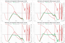
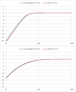
I chose measurements sets I had on hand from a 10” woofer that I think will have similar be response to the Sony SA-W2500 woofer when put in a 1 - 1.5ft^3 box. I am also sticking with a very basic compensation approach of one integrator and one notch filter which will work for almost all subwoofer purposes.
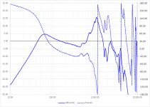
Attachment #1: Here is the response of an accelerometer attached to the dust cap.
It isn’t ideal, resulting in a fairly high Q resonance just above 1khz, but it is representative of what hombre is trying to do.
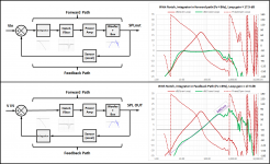
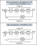
Attachment #2: The upper figure shows the block diagram for the MFB system.
The lower block diagram shows how/where to break the feedback loop and measure the open loop response.
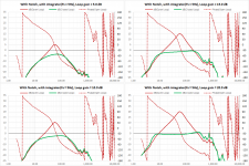
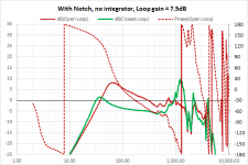
Attachment #3: If a notch filter is used to remove the dust cap resonance. Red curve shows the open loop response, green curve shows the closed loop response. Notice that due to phase problems instability is approached on both ends of the bandwidth, with only 7.5dB of feedback.
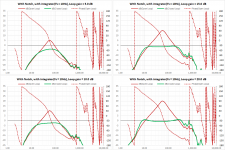
Attachment #4: Adds an integrator with corner point of 50hz and incremental open loop gain.
Attachment #5: Adds an integrator with corner point of 20hz and incremental open loop gain.
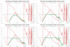
Attachment #6: Adds an integrator with corner point of 10hz and incremental open loop gain.
Attachment #7: Adds an integrator with corner point of 5hz and incremental open loop gain.
Looking at the trends you can see how the integrator adds phase lag which improves stability at both ends of the bandwidth. The lower you place the corner point, the better the LF stability, but the lower the resulting S/N ratio for a given open loop gain. So, you want to use as high a corner point as possible that will give you the bandwidth and feedback factor you are after. I usually aim for > 60deg of phase margin and > 6dB of gain margin.
Attachment #7: There was some discussion of having the integrator in the feedback path rather than the forward path. In this case a signal proportional to cone velocity(not acceleration) is compared with the input voltage. The end result will be an SPL response sloping upward at +6dB/oct since the cone velocity is being held constant.
Attachments
-
 MFB_Example_Int_Location.png138.5 KB · Views: 170
 -
 MFB_Example_Int5_trends.png162.1 KB · Views: 144
 -
 MFB_Example_Int10_trends.png159.9 KB · Views: 138
 -
 MFB_Example_Int20_trends.png159.2 KB · Views: 301
 -
 MFB_Example_Int50_trends.png163.1 KB · Views: 345
 -
 MFB_Example_Notch.png40.1 KB · Views: 345
 -
 MFB_Closed_Open_Diagrams.png50.6 KB · Views: 357
 -
 MFB_Accel_Dustcap.png58.9 KB · Views: 355
That is a bucking magnet, the purpose being to minimize the stray magnetic field around the subwoofer. Back in the day of CRT TVs this was a big deal….subwoofers placed too near a TV often resulted in distorted images and color shifting. Most flat panels TVs are pretty immune to it though.What is the purpose of the second smaller magnet on the back of the Sony W2500 woofer? Why not just make the primary magnet larger?
Since the feedback factor is so low you will likely see little difference. The place that will differ the most will be at the impedance peaks.… if I were to do this and duplicate the above measurements, I am guessing the output across the MFB resistor (WITHOUT MFB circuit active) would be significantly different?
The discussion of MF in the range about 150 Hz reflects the sophistication of posters. But in olden times it was taken as unobtainable and covered a band which was not crying out for fixing. Low notes are crying out for fixing.Perhaps the inductance of the 8” woofer you were using was low. Most subwoofers with 2” or large VCs have inductance > 1mH which rolls off the response and adds extra phase lag exactly where you don’t want it....
If you are thinking of applying enough feedback to make the woofer cone acceleration or velocity follow the input, then I agree. But, if you use very minor amounts of negative velocity feedback like Sony is doing(<3dB), the effect is to add damping at the impedance peaks. The same improvement could be had by using a bigger magnet to lower the Qes. If you didn’t notice, Qes= 1.6 for the Sony woofer. Perhaps Sony decided it was cheaper to add a few opamps and resistors than use a larger magnet?
There are other companies (ie Rythmik and AceBass) that use velocity and current feedback to manipulate not only the damping, but also the effective moving mass and compliance. But, this is not motional feedback in the traditional sense that you are thinking of.
Back to question of what MF is for. Seems to me once again to say, everybody comments on the tightness. But sure, a manufacturer's goal might justifiably be great sound from poor drivers.
About being a way of cutting costs on magnets, that isn't different in kind from lots of places where smarts are substituted for muscle. So, as bad as that sounds to an audiophile, might be OK.
But for me, the goal remains, extending FR downwards by pushing a reluctant cone (and ensuring it is clean) and taming the resonances.
B.
Ben
Last edited:
@hombre,
Thought you might find these PS Audio blog postings which include comments from the designer of the Genesis MFB system of interest.
Measuring change | PS Audio
Getting lucky | PS Audio
Attached is a PDF compilation, in case the pages disappear at some time in the future.
Thought you might find these PS Audio blog postings which include comments from the designer of the Genesis MFB system of interest.
Measuring change | PS Audio
Getting lucky | PS Audio
Attached is a PDF compilation, in case the pages disappear at some time in the future.
Attachments
Thanks bolserst! That read that thread a while back where Paul talks about the the Genesis MFB and Paul's mention / brief description of the piezo and electronics in the Genesis speakers + this diyaudio section is what gave me confident to proceed with this MFB project. As an aside, I have the original pair of Genesis 6.1's with piezo based servo speakers autographed by Arnie Nudell and Bascom King. I would like to be able to duplicate the sound / control / tightness of the bass of the Genesis 6.1's. For those unfamiliar with 6.1's - they have two opposing 12" woofers in about 2 cubic foot enclosure +/- 3 db down to 16Hz.
Might I ask what software you're using to generate the modelled responses?Attachment #1: Here is the response of an accelerometer attached to the dust cap.
When I last worked on this, I wrote my own Matlab scripts to simulate the complex transfer functions of the various elements - integrators, summers, Chebyshev filters, amplifiers - and model the open and closed-loop responses. Raw data for the (driver + piezo) came from an AP System One.
Back then, there wasn't really any open-source software (other than a newborn Linux, still largely useless except to programmers learning about operating systems). I rolled my own, because there wasn't really an alternative.
-Gnobuddy
Agreed, as long as we keep in mind that the BL product and moving mass of the speaker dictate its maximum acceleration per amp of drive current...sort of like amplifier "slew rate" for a loudspeaker driver.About being a way of cutting costs on magnets, that isn't different in kind from lots of places where smarts are substituted for muscle. So, as bad as that sounds to an audiophile, might be OK.
So if the magnet is too small and too weak (to save the manufacturer money), the speaker is inherently going to be "slow", and even motional feedback can only go so far in the attempt to change that.
In fact, MFB will be completely ineffective at maximum power, since voice coil current can't be increased any more in the attempt to produce brisker cone acceleration.
The whole concept would be a bit like putting sophisticated traction control software and hardware on a car, but then installing the cheapest dry-rotted second-hand tires. If there's little grip to start with, traction control can't do a whole lot to improve the situation!
Agreed! One of the joys of the MFB system I worked on was not having to worry too much about the enclosure design. No more delicate balancing act between Thiele-Small parameters and box volume!But for me, the goal remains, extending FR downwards by pushing a reluctant cone (and ensuring it is clean) and taming the resonances.
I was curious what Parts Express might have to offer someone like you, with a taste for deep, clean bass. I found this driver: Dayton Audio RSS390HF-4 15" Reference HF Subwoofer 4 Ohm
It's not cheap by any means (I once bought a brand-new 10" Velodyne subwoofer for less than this driver alone!), but with a 20 Hz free-air fundamental resonance, and a Qts of 0.43, it looks like a great place to start the design of an MFB system. And there's so much cone area that there won't be much need for large cone displacement, making it much easier to provide nice, clean, low-distortion bass.
With a sealed enclosure the size of a college dorm refrigerator, this monster wouldn't need a whole lot of help from MFB to produce tight, flat, bass down to 30 Hz - or probably even 20 Hz - as long as the room didn't mess it up!
-Gnobuddy
Thanks much for driver link.Agreed! One of the joys of the MFB system I worked on was not having to worry too much about the enclosure design. No more delicate balancing act between Thiele-Small parameters and box volume!
I was curious what Parts Express might have to offer someone like you, with a taste for deep, clean bass. I found this driver: Dayton Audio RSS390HF-4 15" Reference HF Subwoofer 4 Ohm
Interesting you comment on not fussing over T/S parameters. I often post (to the annoyance of the wannabes-engineers on the forum) that all you need is a sealed box with just one parameter (volume) that defines the resonance for a given driver and simply the bigger the box the better.
As for that driver link, very nice driver but it has a half-pound moving mass*. That's obese. Much better to keep your eye on parameters that matter and not let weight go nuts. But it ends up high because of an unrealistic notion of how much current has to be pushed through the VC to achieve ridiculously loud output.**
Better to think in terms of good design: strong motor force and light cones and flexible spiders resulting in low free air resonance point.
And then the sim advocates will tell you there's an optimum motor force and an optimum ringing. That's true if your understanding ends with the results that the sim gives you: a little ringing and some weak motor force ratio and your bottom end can boom. Go figure.
MF, as you say, changes those relationships.
Ben
*anyway, still in its box is a dual voice coil driver I just bought for testing VC feedback (who a half-pound mass too)
** the light and nimble Lotus (Elan +2, ahem, ahem) versus the heavy Corvette
Last edited:
Those with soft spider are not available anymore because people would kill them instantly in the field.Better to think in terms of good design: strong motor force and light cones and flexible spiders resulting in low free air resonance point
One of the best of current production : Beyma 15P80Fe. It's already pretty much "self-MFB" from the low Qes, and quite soft suspension and low mass for a 15" driver. Plus does not bottom out easily.
My recent shopping experience as well. Hard to fault buyers for wanting durable drivers.Those with soft spider are not available anymore because people would kill them instantly in the field..
Either I am living in the past or car audio has distorted the market.
B.
Just some thought i compile from what i've learned from the forum about, soft spider : What about cone offset ? Too soft means it will need to be really stable with time to keep voicecoil symetrical to airgap, and need to keep "elastic". Moreover with MFB, if voicecoil get offset for some reason, it should yeld to more and more unlinearity to correct (inductive, BL related, asymetric compliance...), and so more and more gain from mfb... That asymetric problem is often seen in long throw sub klippel test.
New generation PA woofer use silicone spiders...
New generation PA woofer use silicone spiders...
Yes, dynamic DC offset is the big problem today in PA (because sustained high-power sinusodial bass tones are common in modern dance music) and the reason why modern drivers have rather stiff and very progressive suspensions.
MFB does not help here unless the sensor measures excursion (rather than velocity or acceleration) and the control loop is working directly on that -- not easy to implement. With a true position-based servo loop having a well controlled clipping/limiting, the supension could be made as soft as possible. On the other hand, a suspension does not to need to be signficantly softer than the air spring, at least for closed box systems.
MFB does not help here unless the sensor measures excursion (rather than velocity or acceleration) and the control loop is working directly on that -- not easy to implement. With a true position-based servo loop having a well controlled clipping/limiting, the supension could be made as soft as possible. On the other hand, a suspension does not to need to be signficantly softer than the air spring, at least for closed box systems.
OK. So for MF, unless you buy a second-hand dance hall driver and unless you mount it horizontally, a soft suspension (which allows for a light and agile cone) there is no particular obstacle.... except finding one today.Yes, dynamic DC offset is the big problem today in PA (because sustained high-power sinusodial bass tones are common in modern dance music) ...On the other hand, a suspension does not to need to be signficantly softer than the air spring, at least for closed box systems.
Softness per se is no problem. Cones require excursions as needed, whether you have a driver with a soft spider and light cone or stiff spider and heavy cone. Just that with a heavy cone, you need lots of power for the MF to wrangle the cone into truthful position.
B.
Well, one could buy a recone kit for a modern driver and try remove part of the spider, assuming the spider is the dominant factor.except finding one today.
Pretty much all the modeling work I do nowadays for ESLs, woofer/enclosure, EQ filters, MFB, etc I do using Excel. The intrinsic complex number capability makes transfer function calculations a breeze. The plotting capability is not too shabby, and if you need to add additional functionality, you can add VBA routines for FFT/IFFT, convolution, etc. I prefer this approach to the frustration of trying to trick an existing piece of generic software into doing what I want it to. More and more I have also been using it for plotting up measurement data like those I posted since formatting/labeling is easier and it is then in a much more portable format, rather than tied to the measurement software used to acquire the data.Might I ask what software you're using to generate the modelled responses?
If interested, the square-wave visualizer I posted earlier in this thread is completely unlocked, so you can see all the formulas in the cells and the simply VBA routines needed for calculating the square wave response. I threw that together several years ago, and it wasn’t exactly meant for public use so a bit rough around the edges for sure….but should give you an idea of how Excel can be used.
Download file: Post#361
Example plots: Post#256
As others have mentioned, woofers with extremely compliant suspensions are susceptible to having the VC jump inside or pop outside of the gap(gross distortion) when asked to produce low frequencies with peak excursion approaching the physical Xmax value. ie (VC length – gap plate height) / 2.…Softness per se is no problem.
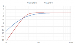
The 12” AR woofer had a moving mass of roughly 100g…so not exceedingly low. The only one I got to measure had Fs = 16Hz and suspension compliance equivalent to about 270ltr (9.5ft^3). There are a few 12” subwoofer drivers out there with similar parameters that will give similar response in similar enclosure sizes. For example, the ScanSpeak 30W/4558T has moving mass of 135g, Fs = 17Hz and compliance of 197ltr. For the 30% increase in mass, you get a much longer voice coil yielding 3x the linear excursion capability (Xmax = 12.5mm vs 4mm). I think that is a pretty good trade.
https://www.madisoundspeakerstore.c...s/scanspeak-discovery-30w/4558t-12-subwoofer/
Attachment #1: Shows response comparison between the two woofers if placed in a small 1.5ft^3 enclosure similar to the AR OEM box, or a large 10ft^3 enclosure. The ScanSpeak gives you equivalent or slightly more extended response with 3x the linear output capability.
Attachment #2: You have asked several times what would happen if you put your AR woofer in a larger enclosure. I’ve been hoping you would take the initiative and model, figure it on the back of an envelope, or measure it yourself. Since you haven’t, I’m not sure if you are really interested in the answer or not. In any case, here is an overlay for your consideration. Ignoring for the moment the potential structural resonance problems with a 10ft^3 enclosure, I’d say AR sized the enclosure appropriately…especially for a woofer with Xmax=4mm.
Attachments
Couldn't ask for a clearer presentation. Many thanks.I’d say AR sized the enclosure appropriately…especially for a woofer with Xmax=4mm.
But is the "right sized" 1.5 cu foot box better? With some easily managed EQ, the bigger box might shine.
Not sure how the AR3 woofer differs, but it has a very satisfying rumble a bit south of 40 Hz. As that region reflects the former bottom region of the recording band, it was truly nice bass, at the time. Not sure why your simulations don't show resonances in the sealed enclosures.
My old AR1 woofer (early model with the thick cardboard cone) is decrepit beyond resuscitation.
B.
- Home
- Loudspeakers
- Subwoofers
- Commercial motional feedback woofer available sort of