Gnobuddy, full ack to your analysis. Something went wrong there in their measurements. Still the baseline holds true, mass per se is not the root cause for a woofer to "sounds slow".
+1Something went wrong there in their measurements. Still the baseline holds true, mass per se is not the root cause for a woofer to "sounds slow".
Notice their statement about how they added the mass:
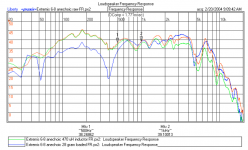
“- Added mass was 28.5 grams (Mms of the Extremis 6-8 is 24.39 grams per Klippel).
Mass added to dustcap only; none was placed on the cone itself (all within the diameter of the former).”
Then look at the frequency response comparison shown on the last page: (attached for convenience)
You can see that at low frequencies the added mass has decreased the SPL by the expected amount, but at high frequencies the SPL is nearly unchanged...with a notch separating the two regimes. Looks like the mass mounted on the dust cap “decouples” from the motion of the VC and cone above 500Hz. Since the high frequencies that define the leading portion of the impulse response, this explains the impulse time histories.
BTW, this is exactly the same problem you run into when trying to mount an accelerometer on the dustcap. The only difference is that you will be dealing with higher frequencies since the mass of the sensor will be less.
Attachments
And I take my hat off to you, sir. You nailed it, and solved the mystery. Thank you! 🙂Looks like the mass mounted on the dust cap “decouples” from the motion of the VC and cone above 500Hz.
Agreed, this was my concern with Hombre's setup.BTW, this is exactly the same problem you run into when trying to mount an accelerometer on the dustcap.
When I did my own MFB woofer, my first preliminary experiment immediately revealed that my most immediate problem would be raising raising the piezo sensor resonance frequencies as high as possible.
So I cut the Tyvek (I think) dust-cap out with an Exacto knife. We had a lathe in the machine shop, and I found a Perspex (Lucite in the USA) rod lying in the junk box. So I machined a short plug out of the Perspex that was a light press-fit in the woofer voice coil's Kapton former. Then I machined a shallow cup at one end, a tiny bit smaller in diameter than the piezo disc.
In the final assembly, the Perspex dust-cap was glued into the voice coil (it had a shoulder that sat on the top edge of the voice coil, for a very rigid coupling between the two). The piezo disc sat on the top of the Perspex piece, supported all around its edge, and glued down to the Perspex. There was a tiny vent hole into the cavity under the piezo, so that the piezo didn't act as a barometer.
With this sort of rigid mount, the first self-resonant piezo mode was a long way above the 1 kHz first woofer cone break-up mode. That's exactly what I needed - now the MFB system would be limited by the woofer performance, not by my sensor's own failings.
It's been a while, but my (rather faint) memory is that, with the piezo disc supported all round the edge in this way, the lowest piezo self-resonance frequency up around 5 kHz or so.
After all these years, I have completely forgotten what glues I used; I do know that I talked to a couple of speaker engineers to find out what glue they recommended for adhering to Kapton.
-Gnobuddy
I agree. At least according to the simple mathematical model, two woofers with same Qts and Fs will have the same frequency response, and if we adjust the input powers so both produce the same SPL, then both will sound equally "slow" or "fast". We'll have identical impulse responses in both cases....mass per se is not the root cause for a woofer to "sounds slow".
I hate even using terms like "slow" here, because it is such a subjective term, and I have no idea what it actually means to anyone!
To me, "slow" suggests that the woofer is driving a room resonance mode, and that resonance is growing exponentially with time as energy is pumped into it, like the sound of a big church organ, giving a perceptible sense of "lagging behind" the woofer, i.e., it will sound "slow".
Then, when the woofer stops moving, the room mode will exponentially decay instead of dying immediately, so the sound will also die out in a slow and laggy way.
If I'm right, this type of "slow" has nothing to do with the speaker at all, but is instead a property of the room, and the coupling between the woofer and room!
-Gnobuddy
I am by no means an expert on this sort of thing, but my instincts tell me that, at the rather low frequencies that subwoofers deal with, probably all we need is the right frequency response (i.e. flat, with gentle fall-off at each end), which, in turn, automatically gives us the right impulse response.But, as with other peculiar discussions on this forum, FR is not the whole story. For example, there is the euphemism, "group delay" which normal people call boom.
And, let's not forget, we need the speaker enclosure to be perfectly rigid and perfectly resonance-free (good luck there!), and, oh yes, we need the room to have no resonant acoustic modes at all (good luck there, as well!)
So my common-sense approach would be to first make the woofer itself "do the right thing" with MFB, then try and make a nice rigid enclosure, then do what little one can to make the acoustic environment better.
Agree 100% about the Lotus, but there is a risk in taking analogies too far.But as Lotus owners will rush to tell you, speed going in a straight line is a small and maybe cheesy aspect of driving pleasure.
ALL automotive handling depends on one very unglamorous fact: the more weight you put on a tire, the less lateral G's it can pull.
The vast majority of drivers are completely ignorant of this fact, and probably, so are the vast majority of auto mechanics.
But when race mechanics or back-yard hot-rodders adjust roll-bar stiffness or change spring rates, what they're really doing is altering the amount of weight on each tire during cornering, changing its grip so that the vehicle's handling changes.
This is why light cars with big tires outcorner heavy cars, all else being the same. Colin Chapman proved this rather dramatically a long time ago, and Mazda Miata owners today can confirm his philosophy.
As far as I can understand, the same physics does not apply in the "light woofer, heavy woofer" situation. The usual simple mathematical model (rigid cone, etc) says that if we can generate exactly the same frequency response from two woofers - same frequency curve, same SPL - then both will be equally "fast", quite literally - they will have mathematically identical impulse responses.
In a sense, as I mentioned before, this is because the two woofers don't have the "same-size tires" - to get the same Qts, the heavy woofer has to have a much bigger magnet.
However, even from the simple mathematical model, the identical acoustic performance doesn't come without a price: the heavier woofer needs a bigger, heavier, and more expensive magnet to get its Qts right. And it needs more audio watts to drive it to the same SPL as the lighter woofer.
In real life, I suspect that other complications will start to pile up, as the woofer gets heavier and heavier. The voice coil has to get rid of more and more heat; the voice-coil former has to resist more and more force without buckling; and so on, and so forth. There are going to be rising costs, and diminishing returns, as one goes down this path.
But if we look at a vintage 1950's guitar speaker (light cone, piddly magnet, high sensitivity, poor rigidity, high Fs), and then at Bob Carver's "Sunfire" woofer (massive cone, humongous magnet, absurdly low sensitivity, high rigidity, very low Fs), we can see the two extremes of this approach at work.
Over the decades, fashion (and audio amp technology) has swung decidedly in one direction, probably for the reasons we discussed earlier on this thread - today's abundance of cheap audio power, and today's low tolerance for large speaker enclosures. In 1950, who could imagine a 500-watt bass guitar amp weighing only 2 kg, and small enough to hold in one hand? But today, you can buy them off-the-shelf: MARKBASS | Bass Amplification
-Gnobuddy
Yes, non-rigid dust cap issues reported again. But an issue at the low freq where MF matters the most? Puzzling that with heavy cones these days, it is so troublesome to craft a rigid girder from carbon fibre (coveted by wealthy motorcyclists) or maybe what's that new isotope of carbon that rhymes with "obscene", something 9?So I cut the Tyvek (I think) dust-cap out with an Exacto knife.
When young, cone fabrication was considered a high art to balance weight, rigidity, modes, internal damping, etc. Today, just mechanical engineering to make rigid. Progress.
Ben
Last edited:
Yes. wrong to belabour remote analogies, but the car comparison is "unsprung weight" and suspension effectiveness. Among other advantages, the Chapman Strut and in-board brakes and light half-shafts resulted in low unsprung weight. That is analogous to a light cone. The car wheels are able to nimbly follow the bumpy road without upsetting the car from its chosen path.
B.
B.
Last edited:
I worked shoulder-to-shoulder with a speaker (driver) designer at one time. As far as I know, these guys do not want a rigid dust-cap. Apparently the dust-cap actually acts as a crude dome tweeter or "whizzer cone", and is often tailored to fill in a hole in the frequency response, or smooth out a bump, or something like that.Yes, non-rigid dust cap issues reported again.
What this guy did was as much black art as hard engineering. He would tweak the driver's high-frequency response by doing things like changing the glue used to attach the dust-cap to the cone, or changing the diameter of the dust-cap a tiny bit!
Yes, but only because of the way servo systems work! To wit:But an issue at the low freq where MF matters the most?
- Good MFB performance means you need a good amount of negative feedback (15 - 20 dB)
- To get 20 dB (that's 10x) of feedback, and keep the servo stable, the open-loop, upper unity gain frequency has to be roughly ten times higher than the speaker resonance frequency. The lower unity-gain frequency has to be roughly ten times lower.
- With, say, a 50 Hz resonance, that means you now need the speaker+sensor combination to behave itself from 5 Hz to 500 Hz, at least. More is better, especially at the high end.
- To get the sensor to behave at 500 Hz, you need a very rigid mount to the voice coil.
Rigid is not what speaker designers want - so why would they bother?Puzzling that with heavy cones these days, it is so troublesome to craft a rigid girder from carbon fibre
You might get a kick out of this: when I was working on my piezo sensor back in 1998 or so, I looked up formulae for stiffness of a beam. Then I added the constraint that the mass of the beam had to be constant, no matter what material it was made out of, and worked out the math until I had a formula I could work with.
What I was after, of course, was a light, stiff piezo mount.
My formula included the bulk modulus (of elasticity) of the material, and its density. A high bulk modulus was good. Low density was also good. (Stiff and light is good, floppy and heavy is bad. Yes, agrees with common-sense.)
Then I ran the numbers for a couple of dozen materials through a simple computer program I wrote (didn't have a spreadsheet at the time), to try and identify a winning material (or materials) that would have the right material properties to make a light, stiff, piezo sensor mount. Basically I ran the numbers for every affordable and easily obtainable material for which I could find the bulk modulus and density numbers.
Of all the materials I compared, guess which ones rose to the top? Better than aluminium, better than steel? Spruce, and balsa wood, and paper!
Spruce - the same stuff they used to build early aircraft out of. Balsa - the stuff they still build model aircraft out of. Aircraft need to be light and strong. Those early aircraft designers knew what they were doing when they picked spruce!
Paper was, IIRC, right up there with spruce. Makes sense, paper is basically wood fibres, after all.
Most of the metals I compared did very badly; all of them were too dense to be worthwhile, even though some had very good bulk modulii. Makes me wonder about all these fashionable aluminium-cone speakers on the market now. Titanium was, I think, the best of the lot; titanium-dome tweeters actually make good engineering sense.
All the common plastics did badly too; they had relatively low densities, sure, but the bulk modulus was always far too low. Light and floppy - not what we want for a rigid beam!
I'm sure carbon-fibre and/or graphene would do very well in such a comparison. I don't think I included either - I'm not sure graphene was even discovered at that time.
-Gnobuddy
The relevant parameter is actually the ratio of sprung weight to unsprung weight. Make the car heavy enough, and you get a smooth ride even with an absurdly heavy cast-iron live rear axle. This is exactly the recipe that Cadillacs and Buicks - and most American sedans - followed until the 1980's or so. It worked perfectly, as long as you drove in a straight line!...the car comparison is "unsprung weight" and suspension effectiveness.
B.
(Cornering brought in the other issue I described - lateral grip - and there, more weight is decidedly not your friend.)
Pushing your analogy to extremes: heavy woofer cone, massive magnet, same Qts: similar to massive unsprung mass, massive sprung mass, massively stiff springs, and massively stiff shocks. End result, exactly the same bump-following ability, from both heavy and light cars, sorry, woofers. Surprise! 😀
Please note, I'm not trying to win an argument for arguments sake - only to understand and describe, to the best of my ability, the physics of a loudspeaker around it's fundamental resonance frequency.
-Gnobbudy
And I take my hat off to you, sir. You nailed it, and solved the mystery. Thank you! 🙂
Agreed, this was my concern with Hombre's setup.
When I did my own MFB woofer, my first preliminary experiment immediately revealed that my most immediate problem would be raising raising the piezo sensor resonance frequencies as high as possible.
-Gnobuddy
Great tips on how you mounted your piezo - thank you.
Again, I reiterate to all those doubting - the way I have mounted the piezo on the firm dust cap of the Sony W2500 and subsequent testing at low volumes is not a problem or concern to me. Why not?
1. The dust cap is sturdy.
2. The piezo is very light - < 2 grams
3. I am testing at low volumes.
4. Testing at low frequency so no or low decoupling.
5. The band pass built into the Sony preamp really obviates any high frequency of significant amplitude getting to the woofer / piezo.
6. As demonstrated thus far, the output waveform from the piezo looks very good.
7. Long term I will mount the piezo on the voice coil but for now, this dust cap mounting is good enough and it is working, and working quite well as shown by the output.
My next hurdle is the electronics. I was hoping to get some 'feedback' 😀 on my small simulation of the Sony sub circuit - simple as clicking the link in my previous post. I think I can pipe in the piezo output into the Sony MFB circuit (with some minor mods) in lieu of the feedback from the MFB resistor - but would like to hear reasons why this wont work.
Why I think this has potential to work (coming from a neophyte who only has limited circuit analysis understanding from watching youtube videos):
1. The unconditioned waveform from the piezo looks similar to the waveform from the MFB resistor, varying in amplitude and phase.
2. Looking at the Sony MFB sub circuit, it appears to have in integrator already built in (IC202). I also think this is a difference amplifier ?
3. I have a spare dead pair of Genesis servo amps - looking at their circuit, it appears to have: piezo -> difference / buffering amp -> integrator/filter -> differential amplifier where the preamp signal comes in and mixes with the piezo input. 3-op amps.
4. Recalling Paul McGowan's post summarizing this (3 parts) is what it took to get their servo system working.
5. I would like to know where pin 3 goes on the Sony sub circuit..is that ground?
Sony MFB sub circuit

Last edited:
Unfortunately, I can't tell much from that simulation. To actually design a servo system from scratch, you really need both the gain/frequency plot, and the phase/frequency plot, of the entire system (amp, speaker, piezo, piezo electronics). And then you tweak the whole thing so it gives you negative feedback, and no phase problems in the passband (region where loop gain is greater than unity.)I was hoping to get some 'feedback' 😀 on my small simulation of the Sony sub circuit - simple as clicking the link in my previous post.
As a loose analogy, the process I just described is like a dressmaker measuring a customer, and then tailoring a custom-fit wedding dress for her.
What you're proposing, on the other hand, is a little bit like asking "My grandma was 5' tall and weighed 80 lbs. I still have her heirloom wedding dress. Will it fit my niece, whom I haven't seen in 20 years, and who is planning to get married soon?" 😀
And I would say "The odds are against you, my friend, but you never know till you try!"
Why not try the wedding dress, sorry, experiment, and see? I think the experiment might be illuminating.I think I can pipe in the piezo output into the Sony MFB circuit (with some minor mods) in lieu of the feedback from the MFB resistor - but would like to hear reasons why this wont work.
I would take a couple of preliminary steps first, though, to prevent damaging anything if things go badly. Then, just connect it up, and find out for yourself what happens!
Protective step #1: put a power resistor between the speaker and amp output. Say 47 ohms, and rated for a watt or two. If your servo goes violently unstable, the resistor will protect the woofer and amp by drastically limiting power delivered from the amp, and to the speaker. At worst, the resistor itself will smolder to death, but resistors are cheap!
Protective step #2: put a pot between the output of your servo conditioning electronics, and the place where the negative feedback signal is mixed with the input signal. With the pot at zero, there will be no feedback whatsoever. As you turn up the pot, you add motional feedback. If the amp takes off and oscillates, quickly back off the pot, while that 47 ohm resistor takes the heat (literally).
Now, with the 47 ohm resistor in place, you have drastically cut the loop gain; if the woofer is nominally 4 ohms, you've effectively inserted a voltage divider in the loop that cuts the signal by a factor of roughly thirteen times. If the woofer is 8 ohms, you've cut the loop gain by a factor of seven times.
In either case, you must make up the deficit by adding extra gain in the feedback loop; temporarily put in a non-inverting opamp stage with a gain of x13 (four ohm case) or x7 (8 ohm case). The opamp must be connected to make your feedback piezo signal bigger, before it's mixed with the input.
I would also add a pot that lets you control feedback signal amount from zero to full; you will have zero feedback at one end, and full (maybe too much) feedback at the other.
With all this done, set the feedback pot to zero, close your feedback loop, and power up. With zero feedback, everything should remain stable.
Now feed in an audio signal of suitable frequency (middle of woofer passband). Monitor woofer voltage - it will drop as you add negative feedback, if everything works properly. Gradually dial up your feedback pot; paying attention to the woofer voltage as you go.
One of two things will happen:
Possibility one (the dress fits your niece, after all): Your woofer signal will fall by "x" dB, where "x" is the amount of negative feedback you've always dreamed of having in your MFB system. Success! You can now power off, remove that extra x13 or x7 gain stage, remove the protective 47 ohm, drop the feedback pot back to zero, and power up again. Once again increase feedback until you have your "x" dB of gain reduction. Done. Celebrate. Enjoy the new MFB system.
Possibility two (the dress doesn't fit): As you turn up the feedback pot, and long before you get to your "x" dB of signal reduction at the woofer, the electronics bursts into oscillation. The 47 ohm resistor smokes, while you rush to turn the feedback down to zero as quickly as you can. Ouch. The old Sony electronics won't do the job, and you have to design the servo electronics from scratch.
Well, at least you're no worse off than before, once you remove that smelly, slightly burned 47 ohm resistor!
-Gnobuddy
Anybody ever thought of (or actually tried) a composite sensor approach for a wide-band MFB control loop, provided a suitable driver is used (benign breakup etc)? Acceleration sensor (piezo) for HF, velocity (sensor coil) for MF and position (hall-effect, laser, RF-capacitive) for LF?
Since position falls 40dB/decade and velocity falls 20dB/decade I would think this could lead to better S/N and resolution as each sensor is used in the region where its output highest, and better linearity. Position servo down low would have the advantage of nailing down voice coil dynamic centering.
Next question, anybody even tried higher order feedback loops not governed by a dominant pole alone? With composite (nested) opamps this technique works very well even though it is counter intuitive wrt stability as the open loop response phase looks very sketchy but then I learned from the great Gerald Graeme that "phase only matters at the intercept" and could successfully build composite amps.
Last edited:
As a loose analogy, the process I just described is like a dressmaker measuring a customer, and then tailoring a custom-fit wedding dress for her.
What you're proposing, on the other hand, is a little bit like asking "My grandma was 5' tall and weighed 80 lbs. I still have her heirloom wedding dress. Will it fit my niece, whom I haven't seen in 20 years, and who is planning to get married soon?" 😀
-Gnobuddy
Great analogy - who would have thought that haute couture could be applied to MFB!
Thank you, Sir, for the lucid guidance and sharing your expertise - very helpful. I hope I can get some kind of progress report posted in the next couple days.
I've seen an approach like this used for a laser that was frequency-stabilized to an extraordinary extreme. The laser had one mirror with a voice coil acting on it, working up to a few hundred Hz, making relatively slow, relatively large corrections to the frequency of the light beam.Anybody ever thought of (or actually tried) a composite sensor approach for a wide-band MFB control loop, provided a suitable driver is used (benign breakup etc)?
Another laser mirror was mounted on a piezo that took over at frequencies above the voice coil, and acted up to a few kHz. Much less movement available this time, but able to make fast, albeit small, frequency corrections.
And at even higher frequencies, there was a Kerr cell in the laser's path. A Kerr cell is a device that changes refractive index in response to electric field; in effect, applying a voltage to it changes the speed of light itself as it travels through the cell. Modulating this voltage appropriately allowed very fine - but very fast - control of the laser frequency.
The servo electronics was something to behold - racks and racks of hand-built, custom-designed, electronics.
The whole thing worked very well, but was also a bit like a house of cards; if the voice-coil servo lost control, the other two finer servos riding on its back would, of course, also lose control. Then you would see multiple frazzled scientists running around twiddling knobs and muttering to each other, until they finally got their house of cards back up again.
So I know that what you are suggesting is possible. But I think it might be a pretty complex solution. Probably well beyond my own servo design capabilities.
I thought about it, but never tried it. One reason I didn't pursue this is that these types of more complex servo networks tend to be conditionally stable - if the open-loop gain changes, the servo suddenly becomes unstable.Next question, anybody even tried higher order feedback loops not governed by a dominant pole alone?
If the woofer voice coil was ever driven part-way out of the magnetic gap during a big transient, that would lower the overall loop gain of the servo.
My concern was that this drop in gain might be enough to make a conditionally stable servo loop no longer stable. If that ever happened, the servo would instantly burst into full-power oscillations. Bye-bye, woofer, and, as this was to be a commercial product, bye-bye, customer!
In the end, I got 18 dB of very stable, very well-behaved feedback, without having to resort to a super-complex servo, so I didn't push beyond that point.
-Gnobuddy
Thanks for your exellent input.
Yes, this might be the major point of weakness. One would need to chose a very conservative approach wrt possible changes in open loop gain which pretty much defeats the whole idea, given the small operating bandwidth any net improvement of open loop gain would be minimal.if the open-loop gain changes, the servo suddenly becomes unstable.
If the woofer voice coil was ever driven part-way out of the magnetic gap during a big transient, that would lower the overall loop gain of the servo.
Phase of piezo vs resistor MFB readings
After reading and re-reading your, bolserst's, steph_tsf and other's posts, coupled with my recent observations of scope waveforms - noting the frequency dependence of piezo vs resistor MFB outputs - I think I am finally understanding the admonitions about phase and its critical importance to MFB. But I have a question - let me first try to succinctly summarize my observations of simultaneously looking at output from piezo and across MFB 0.22 ohm resistor.
IN OEM PORTED BOX - PLUGGED PORT:
1. From about 200 Hz down to 80 Hz, the waveform output phase of the piezo and MFB resistor are in good agreement (approximately in phase). Amplitude of piezo is greater than the MFB resistor.
2. From about 80 Hz down to 40 Hz , the phase of the waveform output of the piezo shifts 180 degrees relative to the MFB resistor. Amplitude of piezo relative to MFB resistor decreases and at this frequency range is about the same amplitude as the MFB resistor
3. From about 40 Hz down to 28 Hz, the phase of the waveform output of the piezo shifts continues to shift relative to the MFB resistor. Amplitude of piezo has decreased below the the level of the MFB resistor.
4. UNPLUGGED PORT: Unplugging the port changes the phase shift of the piezo output but not the MFB resistor. Around 44 Hz, piezo and MFB resistor are in phase, shifting 0-360 out of phase from 40-80Hz, being back in phase from about 80-200Hz
Questions:
Why does the output from the piezo appear to invert as the frequency is lowered but the output from the MFB resistor does not?
Why does plugging / unplugging the port seem to only affect the phase of the piezo output and not the MFB resistor output?
To actually design a servo system from scratch, you really need both the gain/frequency plot, and the phase/frequency plot, of the entire system (amp, speaker, piezo, piezo electronics). And then you tweak the whole thing so it gives you negative feedback, and no phase problems in the passband (region where loop gain is greater than unity.)
-Gnobuddy
After reading and re-reading your, bolserst's, steph_tsf and other's posts, coupled with my recent observations of scope waveforms - noting the frequency dependence of piezo vs resistor MFB outputs - I think I am finally understanding the admonitions about phase and its critical importance to MFB. But I have a question - let me first try to succinctly summarize my observations of simultaneously looking at output from piezo and across MFB 0.22 ohm resistor.
IN OEM PORTED BOX - PLUGGED PORT:
1. From about 200 Hz down to 80 Hz, the waveform output phase of the piezo and MFB resistor are in good agreement (approximately in phase). Amplitude of piezo is greater than the MFB resistor.
2. From about 80 Hz down to 40 Hz , the phase of the waveform output of the piezo shifts 180 degrees relative to the MFB resistor. Amplitude of piezo relative to MFB resistor decreases and at this frequency range is about the same amplitude as the MFB resistor
3. From about 40 Hz down to 28 Hz, the phase of the waveform output of the piezo shifts continues to shift relative to the MFB resistor. Amplitude of piezo has decreased below the the level of the MFB resistor.
4. UNPLUGGED PORT: Unplugging the port changes the phase shift of the piezo output but not the MFB resistor. Around 44 Hz, piezo and MFB resistor are in phase, shifting 0-360 out of phase from 40-80Hz, being back in phase from about 80-200Hz
Questions:
Why does the output from the piezo appear to invert as the frequency is lowered but the output from the MFB resistor does not?
Why does plugging / unplugging the port seem to only affect the phase of the piezo output and not the MFB resistor output?
Last edited:
Outstanding cogent aforethought by Gnobuddy (see quote below) - I now have a much better understanding of his previous post #418. And his post helps explain the answer to my above question.
So, based on my observations described above, coupled with Gnobuddy's comments, since piezo output nearly mirrors that of the MFB resistor above ~75-80 Hz, and is out of phase down around 44 Hz - why not just find a woofer with resonance of 18-20Hz or lower, and just use piezo to MFB control ~30Hz and above? One may not get the deepest notes but those 30Hz and above would be well controlled and crisp. Or get a 'woofer' with a very high resonance and just power through at low frequencies, all shifted out of phase...no need to worry about phase correction.
'Woofer' example with high BL, low mass and high resonance:
https://www.madisoundspeakerstore.com/approx-8-midrange/audax-hm210z10-8-aerogel-midrange/
Down around it's fundamental resonance frequency, a speaker itself acts as a second-order high pass filter. If you had a perfect piezo sensor (or other accelerometer) mounted to the voice coil, it would accurately reproduce that second-order high pass filter response.
Here's what that means: well below the resonance frequency, you have 180 degrees of phase lead. If the speaker was perfect (no cone break up), then you'd have zero phase shift at all frequencies well above the resonance frequency.
And even in this ideal world (perfect speaker, perfect sensor), you already have a problem: no matter what you do, 180 degrees of phase shift in the speaker+piezo system means you will have positive feedback either below the speaker resonance, or above it. So you can choose between either a loud uncontrollable howl below the speakers Fs, or above it!
-Gnobuddy
Last edited:
Assuming you're feeding the piezo into a sufficiently high input resistance, the piezo signal corresponds to the woofer cone acceleration.Why does the output from the piezo appear to invert as the frequency is lowered but the output from the MFB resistor does not?
The MFB resistor signal, on the other hand, is a (crude!) approximation to the woofer cone velocity.
For a sinewave signal, there is inherently a 90-degree phase shift between velocity and acceleration. These two quantities (velocity and acceleration) also have different slopes as frequency changes - different frequency responses.
So any resemblance you see between the piezo signal and current-sensing resistor signal are more or less coincidental. Not quite chalk and cheese, perhaps, but more like baby elephant vs. tapir.
(And so we segue from haute couture to zoology, quite seamlessly. 😀 )
Excellent experiment! Now, this is very interesting!Why does plugging / unplugging the port seem to only affect the phase of the piezo output and not the MFB resistor output?
The piezo is reporting what the woofer cone is actually doing. Plugging the port changes the air pressure in the box, in a way that varies with frequency (port tuning), and so changes the cone motion. The piezo is telling you about this change in cone motion. No surprise there.
If the coil current sensing resistor was actually telling you the cone velocity, then it should also report changes in cone motion as the port is plugged and unplugged.
The fact that the current-sensing resistor signal is not showing any changes in response to the port, tells us that this signal isn't actually reporting cone velocity at all!
I don't want to start beating a dead horse, but you may remember that, earlier in the thread, I was quite skeptical about the voice coil current being any sort of accurate feedback signal. The problem is that this signal is corrupted by voice coil resistance, corrupted by voice coil excursion, corrupted by voice coil inductance, corrupted by non-uniform magnetic field, corrupted by changes in audio power (which changes voice coil resistance), and corrupted by changes in temperature (which affect the magnetic properties of the Ferrite magnet.) That's a lot of corrupting. 😱
It would seem that your experiment has confirmed my distrust of this current signal, and of this approach to "MFB". If your experimental data is accurate, you have just shown that MFB using coil current isn't really motional feedback at all, since the signal being used for feedback doesn't actually represent cone motion!
-Gnobuddy
Attachments


Experiments sometimes need replicating. The cone motion with a nicely tuned BR box is greatly reduced compared to free-air and shifted compared to a sealed box and all bets off just "plugging" the port.If the coil current sensing resistor was actually telling you the cone velocity, then it should also report changes in cone motion as the port is plugged and unplugged.
The fact that the current-sensing resistor signal is not showing any changes in response to the port, tells us that this signal isn't actually reporting cone velocity at all!
I don't want to start beating a dead horse, but you may remember that, earlier in the thread, I was quite skeptical about the voice coil current being any sort of accurate feedback signal. The problem is that this signal is corrupted by voice coil resistance, corrupted by voice coil excursion, corrupted by voice coil inductance, corrupted by non-uniform magnetic field, corrupted by changes in audio power (which changes voice coil resistance), and corrupted by changes in temperature (which affect the magnetic properties of the Ferrite magnet.) That's a lot of corrupting. 😱
...
If your experimental data is accurate....
Many people have used the simple series resistor sensor. A bridge is not a whole lot different except it magnifies the back EMF component by nulling-out various other factors, some of which you have named.
You are right in naming all those corrupting factors and more. But are they large enough and prevalent enough at ordinary listening levels to sweat over?
Again we see a difference in perspectives. For me, just putting a hit on the system resonance and group delay and maybe reducing that 10% THD at low frequencies is a significant step forward - and easy to accomplish. For others, reducing distortion to very low levels and removing all faults up to 1kHz is a goal.
Ben
Last edited:
Ben, to reduce distortion, we need a feedback signal that accurately represents cone movement. Without that, there is distortion in the feedback signal, and it only adds more distortion to the speaker.
This is why I have no trust in the current-sensing and bridge-nulling feedback methods. They are easy to implement, and nearly zero cost, which is their appeal; that's why people (and corporations) try them, but I have no faith in the quality of the feedback signal they provide.
But you are entirely right, I have no hard data on them at this time, only my instincts. It's always possible that I'm quite wrong in my opinion. It would be nice to have that hard data, so we'd know for sure, one way or the other.
The only other thing I'd like to clarify, is that to reduce distortion at 30 Hz by, say, a factor of 10, you automatically need a closed-loop bandwidth from 3 Hz to 300 Hz (one-tenth, and ten times, 30 Hz, respectively.) This follows from the characteristics of the dominant-pole servo stabilization method that all these MFB systems use.
So it's not that I think MFB will reduce distortion at 1 kHz - I doubt that is even possible, since the speaker cone is no longer rigid at such high frequencies, and doesn't follow the voice coil motion exactly. The fact of the matter is that, to substantially reduce distortion at, say 50 Hz, the servo must operate up to several hundred Hz; if you want 20 dB distortion reduction at 50 Hz, the servo must operate up to 500 Hz.
It seems that the particular Sony subwoofer that kicked off this thread only used just a few dB of feedback. That isn't enough to do anything useful, so I can't help but see it as mainly a marketing gimmick, sad to say.
I really wonder if there is any promise in the "put a microphone just in front of the speaker for a sensor" idea. There may be - Maxell used to make a line of noise-cancelling headphones that used a tiny electret microphone inside the headphone cup to sense external noise, and feed it back to the electronics so as to cancel it.
In the process, of course, those tiny little microphones also feed back the sound from the headphones themselves. So these are genuine MFB headphones - and the extended and very accurate bass from them told me so the first time I tried them on. I ended up buying them for the best bass I'd ever heard from headphones, rather than for their rather ineffective noise-cancellation properties.
-Gnobuddy
- Home
- Loudspeakers
- Subwoofers
- Commercial motional feedback woofer available sort of