Very true, using the voice coil as its own velocity sensor is questionable. It's hard to isolate the pure velocity component v(t) from the voltage drop accross the static impedance Zs (which isn't static, actually) and, more importantly, once the coil is pulled out of the gap this "microphonic voltage" is giving a wrong signal, less than actual velocity: Measuring veloctity via the equation Terminal Voltage = BL*v(t) + i(t)*Zs requires that BL is a constant (as well as Zs).Ben, to reduce distortion, we need a feedback signal that accurately represents cone movement. Without that, there is distortion in the feedback signal, and it only adds more distortion to the speaker.
This is why I have no trust in the current-sensing and bridge-nulling feedback methods. They are easy to implement, and nearly zero cost, which is their appeal; that's why people (and corporations) try them, but I have no faith in the quality of the feedback signal they provide.
This leads to the surprising effect that the drop of BL causes way too much force injected because the force factor has decreased (but it still is inside of corrective feedback so this has no effect on the closed loop). Cone showns massive overshoot (expanding odd order distortion) once it leaves the gap and that is a disaster unless you have a limiter/clipper ahead and/or a very progressive suspension that limits the excursion (by essentially dropping system loop gain to actually disable the feedback) and/or little feedback at work to start with.
In modern drivers with very low Qes this overshoot from too much self-MFB is also happening and (hopefully) the designers chose a suspension that perfectly compliments this so that total linear excursion is maximized and overshoot is definitely eliminated. In fact by choosing a proper drive impedance you can adjust this large-signal distortion mechanism in a certain range, that is you can shape the "distortion knee" somewhat.
Last edited:
Gnu Octave should work just fine.…My personal life is Microsoft-free (and also Apple-free)…There is probably a suitable open-source computing language option out there somewhere (one possibility is Gnu Octave, a Matlab-alike.)
Another alternative would be Libreoffice Calc.
It is as capable as Excel, although the macro programming language is (frustratingly) slightly different.
Correct. The VC current is simply the applied voltage from the amplifier (Vamp) divided by the woofer impedance. Not sure if you had read thru the early parts of this thread, but the velocity feedback approach was discussed quite a bit. The easy way to get the velocity feedback signal is to use the output of a second VC. The alternative is to consider that the net voltage producing the current thru the driven VC is made up of the complex sum of two parts, 1) the signal from the amp, 2) the back EMF from the woofer. This net voltage divided by the blocked impedance(DC resistance + lossy inductance with no VC motion) gives the net current thru the VC. The back EMF is what we are interested in since it is proportional to the velocity of the VC motion in the magnetic gap. Unfortunately Vamp is larger in magnitude and dominates the sum of these two voltages over all of the frequency range, except at resonance. A bridge circuit can be used with Vamp applied on one side of the bridge and the voltage across the current sensing resistor applied to the other. In theory, if the bridge is carefully balanced, the Vamp contribution is removed from the sensed voltage leaving only the back EMF signal that we want. Of course, in practice the woofer lossy inductance and temperature dependent resistance makes perfect balance un-achievable. But, flattening of the response with MFB in a sealed box is easily achieved at and below resonance where the loss inductance terms or minimal. One nice thing about using the velocity signal for MFB is that the phase is always in the +/-90deg range so essentially no compensation is required to achieve loop gains of 20dB to 30dB…you just need to get the feedback polarity correct. Surprising to me, the system is extremely stable even when woofer is driven to large excursions or the amp is clipped. The not so nice thing is that the feedback signal has the same nonlinearity as the BLi product so little if any distortion reduction is obtainable except at very low frequencies where the suspension distortion dominations. For frequencies < 25Hz, I could often get 2x to 3x reduction of distortion using 25dB of feedback. Above 30Hz, distortion was unchanged or (more often) increased by 2x to 3x.…If your experimental data is accurate, you have just shown that MFB using coil current isn't really motional feedback at all, since the signal being used for feedback doesn't actually represent cone motion!
Posts describing the bridge arrangement:
Post#298
Post#321
Post#357
Post clarifying the bridge arrangement Sony is using:
Post#388
Post comparing measured velocity signals from bridge and 2nd voice coil methods, showing signal “contamination” from inductance and temperature variation.
Post#209
OK, a bridge balanced for blocked VC impedance is back.
#292 shows the feedback signal if you did use the rudimentary resistor sensor. Seems to grab the speaker at the resonance.
B.
#292 shows the feedback signal if you did use the rudimentary resistor sensor. Seems to grab the speaker at the resonance.
B.
Last edited:
3, 4, & 5 do not in any way avoid instability problems.…the way I have mounted the piezo on the firm dust cap of the Sony W2500 and subsequent testing at low volumes is not a problem or concern to me. Why not?
1. The dust cap is sturdy.
2. The piezo is very light - < 2 grams
3. I am testing at low volumes.
4. Testing at low frequency so no or low decoupling.
5. The band pass built into the Sony preamp really obviates any high frequency of significant amplitude getting to the woofer / piezo.
6. As demonstrated thus far, the output waveform from the piezo looks very good.
MFB systems will oscillate whether there is an input signal or not.
Since you have the capability, why don’t you monitor the piezo and sweep up in frequency from 100Hz to 5000Hz. See if there is a response peak and accompanying phase reversal anywhere in that range. This is information you need to know to design the feedback loop circuit.
Yes, it is a remote sensing of the ground at the woofer terminals.5. I would like to know where pin 3 goes on the Sony sub circuit..is that ground?
With high currents running in the woofer, there will be some voltage drop along the printed circuit trace for the ground running to the woofer. Using the remote sensing ground rather than a ground local to the op-amps avoids contaminating the feedback signal with this voltage drop.
Last edited:
I dropped out of the thread for a while at about that point, because I have little personal interest in these kludged schemes that use an inaccurate feedback signal.Not sure if you had read thru the early parts of this thread, but the velocity feedback approach was discussed quite a bit.
And the problem here is that, given their physical proximity, the two coils also act as an audio transformer. The coil that's supposed to sense cone velocity, therefore, also has its output signal corrupted by the drive current through the primary voice coil.The easy way to get the velocity feedback signal is to use the output of a second VC.
When I was about 8 years old, I began building AM radios, and kept it up for the next five or six years. A lot of those radios used air-cored transformers, just two coils in the same general vicinity. They were extremely effective transformers at 500 kHz. The question was, what would they do at a thousand times lower frequency, 500 Hz, say?
Back when I was working on my MFB system, I had access to speaker driver components, because I worked shoulder to shoulder with two speaker designers. I borrowed a dual voice coil from one of them (no speaker, just former and two coils), drove one coil with an audio signal generator, and looked at the output from the other.
Well, it was quite substantial. Way too much mutual inductive coupling between the coils.
I also tried dropping the voice coil former into a speaker magnet assembly, and repeating the experiment. The presence of the solid metal pole pieces altered the mutual coupling between the two coils - if I recall right, things were now much worse than before. With the magnetic core, at least at low frequencies, before eddy current losses in the pole pieces began to dominate, I basically had an audio transformer on my hands!
I can't remember numerical details, probably because I quickly came to the decision that this wasn't an avenue I wanted to pursue any further. Because, once again, the feedback signal wasn't actually an accurate representation of cone motion.
Yes, I do understand this reasonably well. That's why I don't take these feedback methods very seriously (see post #518).The alternative is to consider that the net voltage producing the current thru the driven VC is made up of the complex sum of two parts,
Exactly! You nailed it once again! This is exactly why I don't take this method seriously. It makes no sense to me to go to all the trouble of designing and building the feedback servo electronics, only to throw away the benefits by using an iffy feedback signal.The not so nice thing is that the feedback signal has the same nonlinearity as the BLi product so little if any distortion reduction is obtainable
So 6dB to 10dB of distortion reduction from 25 dB of feedback. Very disappointing.For frequencies < 25Hz, I could often get 2x to 3x reduction of distortion using 25dB of feedback.

Even more disappointing!Above 30Hz, distortion was unchanged or (more often) increased by 2x to 3x.
Thank you very much for sharing your data! Now some of my qualitative suspicions have been confirmed by your quantitative measurements.
-Gnobuddy
OK, back to goals.Exactly! You nailed it once again! This is exactly why I don't take this method seriously. It makes no sense to me to go to all the trouble of designing and building the feedback servo electronics, only to throw away the benefits by using an iffy feedback signal.
So 6dB to 10dB of distortion reduction from 25 dB of feedback. Very disappointing.
Reducing gross LF distortion from 10% to 4% (if I am doing the math right) is a major benefit because the distortion products are much more audible than the fundamental. Going from 10% (probably detectable at 25 Hz and more detectable at 50 and 100 Hz) to 4% is a welcome improvement, even if not on everybody's scale.
Sticking with goals, think about the curious folks lurking on this thread. The forum crowd have good quality or even expensive subs with trick magnetic structures and shorting caps etc. While double-dipping on the motor to derive a VC feedback signal engages Bl error, it does correct what I suspect are far worse non-linearities from the starched fabric spider and rubber rolled surround and maybe even box wall expansion. Anybody have the figures?
Likewise, while harmful to have inductive coupling in a DVC sensor. But how unlinear is that coupling? Can it be remediated using a bridge?
if you are a manufacturer like Philips and want to take an inexpensive driver and make it very good, maybe VC feedback isn't helpful. But if you are a DIYaudio experimenter, maybe it is just fine to start with.
Ben
Last edited:
And maybe you're entirely right about that! 😀...maybe it is just fine to start with.
Ben
Like many of us on this forum, I suffer from a sometimes-debilitating case of perfectionism. It's like having an internal editor who, without using words, somehow communicates the message "Don't even bother starting on this, unless you're going to do it perfectly!"
So, sometimes someone like Ben has to grab my shoulders, and shake me a few times, before I realize he's right. Yes, there is much fun to be had, and much progress to be made, even when nothing is done "perfectly"!
Off topic, but I have an ongoing electronic project that has been on hold for two or three weeks because I can't find a way to finish it "perfectly". Perhaps I should just go finish the bloody thing, warts and all!
-Gnobuddy
Agreed. This is exactly what I was showing in Post#209. In addition, I was trying to show that the signal from the resistive bridge arrangement is corrupted above resonance in exactly the same fashion. The reason being that the same inductance that unbalances the bridge forms a voltage divider with primary winding resistance of the DVC “transformer”, basically forming a HP network for the signal mutually coupled to the sensor coil. I took the first plot from Post#209 and sketched in what the velocity signal SHOULD look like if there was no mutual coupling, or inductance unbalancing the bridge.… the problem here is that, given their physical proximity, the two coils also act as an audio transformer. The coil that's supposed to sense cone velocity, therefore, also has its output signal corrupted by the drive current through the primary voice coil.
I try my best to just let the data do the talking.Now some of my qualitative suspicions have been confirmed by your quantitative measurements.
BTW, I don’t consider experimentation with velocity based MFB as wasted time. How else are you going to understand the possibilities and the weakness of a given approach if you don't study it? Also, I definitely understand the physics and modeling of dynamic drivers much better because of it.
I hear that...😱I suffer from a sometimes-debilitating case of perfectionism.
Wise words from another thread:
“Lets not make "being perfect" be the enemy of "being good".
Sometimes we need what works satisfactorily not what is perfect.”
That being said, VC based MFB has a lot of drawbacks.
The only real strength I found was that it is relatively easy to produce a stable system.
Attachments

The voltage induced into the second VC is affected by all the nonlinearites that affect the inductance of the driver while in motion. But, the biggest problem with the inductive coupling is that above resonance where the back-EMF signal is falling at -6dB/oct it is increase by +6dB/oct and quickly becomes the dominate voltage coming from what is supposed to be a velocity sensor. The velocity signal is completely corrupted and no longer proportional to velocity. The best approach is to use drivers that have a very low inductance to resistance ratio. This pushes the onset of signal corruption up in frequency... while harmful to have inductive coupling in a DVC sensor. But how unlinear is that coupling? Can it be remediated using a bridge?
Unfortunately, a bridge is not a remedy.
Remember the measurements in Post#209 show that DVC and bridge sensors are similar corrupted.
For me, just putting a hit on the system resonance and group delay and maybe reducing that 10% THD at low frequencies is a significant step forward - and easy to accomplish.
If your main concern is properly damped system resonance and defining group delay to your liking, you can do this more easily with properly chosen woofer/enclosure and applying EQ if required,than you can with MFB. Remember, as we discussed earlier in this thread, group delay is just a measure of how quickly phase is changing. Since woofers are minimum phase devices, the phase response is directly tied to the magnitude response. So, defining the abruptness of the LF corner and the roll off slope and you have defined the group delay. They are inseparable.… FR is not the whole story. For example, there is the euphemism, "group delay" which normal people call boom.
For the same reason that they don’t show up when measured or listened to...they aren’t there or are properly damped. I have worked with several similar Peerless woofers and they measure and sound just like the plots look. Properly designed sealed enclosures won't show any resonances at the low end of their frequency response....Not sure why your simulations don't show resonances in the sealed enclosures
Hmmmm...just to make sure I haven’t missed your point, what resonances are you talking about?
1) The woofer/enclosure mass-spring-damper resonance? With these woofers low Qts, this resonance is well damped until enclosures get << 1ft^3. I could overlay the impedance curve so you could see where the peak in the impedance curve is, but the acoustic output is not proportional to the impedance unless you are driving the woofer with a current source amplifier.
2) Internal standing waves in the enclosure? There is absorptive wadding in the sealed enclosures that effectively damps these.
3) Structural panel resonances in enclosures? I cheated a little assuming even for the 10ft^3 enclosure you could find a way to build it stiff enough to not have panel resonances in the passband.
Since you have the capability, why don’t you monitor the piezo and sweep up in frequency from 100Hz to 5000Hz. See if there is a response peak and accompanying phase reversal anywhere in that range. This is information you need to know to design the feedback loop circuit.
Good suggestion, but output drops off above 200 Hz and above ~ 1200 Hz, I am not getting much of a signal output from anything - piezo, MFB resistor, stereocilia of hair cells in my Organ of Corti.
Yes, it is a remote sensing of the ground at the woofer terminals.
With high currents running in the woofer, there will be some voltage drop along the printed circuit trace for the ground running to the woofer. Using the remote sensing ground rather than a ground local to the op-amps avoids contaminating the feedback signal with this voltage drop.
Thank you - very helpful and informative!
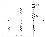
I have a hunch that a strategically sized capacitor in the diagonally opposite arm of the bridge might compensate for the voice coil inductance (at least to first order). No time to work out the math right now, so I may be wrong, but see the attached figure for the concept. (C* is the compensation capacitor I'm proposing; Ls is the speaker inductance, Rs the speaker resistance.)...the same inductance that unbalances the bridge forms a voltage divider with primary winding resistance of the DVC “transformer”, basically forming a HP network for the signal
Of course this won't solve any of the other serious problems that the dual voice coil feedback approach has.
Oh, I studied it, enough to see huge flaws, so I didn't go ahead and build it. You don't actually have to taste a rotten apple to know it's rotten, as they say! 😀How else are you going to understand the possibilities and the weakness of a given approach if you don't study it? Also, I definitely understand the physics and modeling of dynamic drivers much better because of it.
My first step was the same one you mentioned, understanding the physics of the driver through physical modeling. I knew I'd never properly understand the system using Thiele and Small's electrical equivalent approach, I needed to see the equations in terms of masses, springs, and damping, so that's what I set out to create. And I did.
-Gnobuddy
Attachments
And maybe you're entirely right about that! 😀
Like many of us on this forum, I suffer from a sometimes-debilitating case of perfectionism. It's like having an internal editor who, without using words, somehow communicates the message "Don't even bother starting on this, unless you're going to do it perfectly!"
.....
Perhaps I should just go finish the bloody thing, warts and all!
-Gnobuddy
And now, to represent the opposite end of the spectrum - from the just wing it impatient & impetuous crowd, I proudly present my first circuit - noise and all.
Based on GnoBuddy's suggestion about using an integrator to shift the phase shift of the piezo - here is what I think I made - piezo --> difference buffering op amp --> integrator op amp. Snapshot is @ 40 Hz - Lots of noise spikes (BLUE TRACE) but now fairly in sync with the output from the MFB resistor (YELLOW TRACE. [Scale Blue - 50 mv/div; Yellow - 20 mv/div]

My concern (besides the noise spikes) is the piezo output wave still seems to invert, or at least shift significantly sweeping from say 24 Hz to 40 Hz... hmmm?
I think I should take the woofer out of the box...I think the port / woofer / back pressure / resonance interplay are obfuscating the results.
Once I..and when I say I, I am implying the much more erudite posters on this board, make suggestions to help me get this fixed -
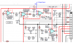
Here is what I am thinking - still thinking...I just incorporate the integrator into Sony's MFB circuit...specifically IC201 (2/2) buffer (see attached figure below)...seems IC201 (2/2) is just sitting there waiting for me to slap a resistor and capacitor in parallel from output to inverting terminal (making proposed integrator in situ) instead of the direct connection that is there now.

Hombre - I confused myself briefly earlier in the thread, as to where exactly the integrator goes. In the process, confused everyone who paid attention to my posts, as well.
What we need is:
input buffer > mixer > integrator > power amp > speaker > piezo > piezo conditioning > mixer.
There will always be a phase inversion as you sweep through the speaker resonance. Without the integrator, you go from 180 degrees lead (below Fs) to zero degrees (above). This is bad - it will be positive feedback on either one side of Fs, or the other.
The integrator adds 90 degrees lag everywhere. That means the 180 degrees lead below Fs now becomes only 90 degrees lead, which is stable inside an NFB loop. At the same time, the 0 degrees above Fs now becomes 90 degrees lag, which is also stable.
The integrator does one other thing; it rolls off the open loop gain as the frequency climbs. This is necessary, because the speaker cone break-up will start to add lots more phase as you go higher in frequency, and this excess phase will make your servo oscillate. The cure is to drop the gain to less than unity by the time you arrive at dangerous amounts of phase lag; if the gain is less than unity, the servo can't oscillate.
-Gnobuddy
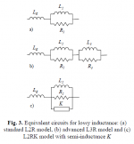
That strategy works in theory, and is documented in several patents. However, since woofer inductance is rather lossy(phase angle closer to 45deg than 90deg) you need to include some resistance in series with the capacitor to improve the compensation. I found to get good compensation for 4 octaves or so, I needed to use the L3R model shown in attached pic for the woofer lossy inductance. Compensation required three cap-resistor pairs in parallel with the lower arm of the bridge. All worked well at lower excursion levels. At higher currents and excursion levels the inductance of the woofer is modulated and you could see the bridge going cyclically in and out of compensation.I have a hunch that a strategically sized capacitor in the diagonally opposite arm of the bridge might compensate for the voice coil inductance (at least to first order).
Lossy Inductance model pics taken from:
http://www.artalabs.hr/papers/mateljan-ela-02.pdf
Other papers of interest on modeling woofer lossy inductance:
http://www.bnam2012.com/papers/Thorborg_31.pdf
http://www.bnam2012.com/papers/Thorborg_32.pdf
Improved Blocked Impedance Model for Loudspeakers
BTW, I just noticed that ScanSpeak has started providing the lossy inductance modeling parameters at the bottom of their woofer spec sheets. Nice!
Attachments
Last edited:
Hmmmm...sounds like you must be feeding the signal into the input of the Sony and the built in LP filter is doing what it was designed to do 😉Good suggestion, but output drops off above 200 Hz and above ~ 1200 Hz, I am not getting much of a signal output from anything
The easiest thing to do is drive the woofer with a separate full range amplifier when doing the sweep. Alternatively, if you want to keep using the Sony amp, you can add an additional input to pin2(not pin3) of the mixer as shown in attached figure. This may also come in handy later when you are trying to perform open or closed loop measurements and want to avoid confusion from the preamp crossover and EQ boost.
Attachments
Last edited:
Yikes! What a can of worms! 😱...to get good compensation for 4 octaves or so, I needed to use the L3R model...
...the inductance of the woofer is modulated and you could see the bridge going cyclically in and out of compensation.
You've just tripled my distaste for these attempts to ferret out a useful feedback signal from the voice coil driving voltage or current. 😀
Once again, thanks for sharing all these interesting results from your experiments!

-Gnobuddy
Hombre - I confused myself briefly earlier in the thread, as to where exactly the integrator goes. In the process, confused everyone who paid attention to my posts, as well.
What we need is:
input buffer > mixer > integrator > power amp > speaker > piezo > piezo conditioning > mixer.
-Gnobuddy
I have created my first schematic in LTSpice (based in part on Steph_tsf's post with Sony schematic to try to illustrate my thinking about using existing Sony MFB circuit to condition the piezo circuit. In the below schematic, I compare the Sony MFB circuit to the circuit on the preamp from my servo loudspeakers that I have tried to figure / trace out (some values missing so far). I am a bit rushed for time but wanted to get this posted before I leave. I also offer my totally amateur rendition of what I think some of these components are doing. My parlance may be incorrect but here goes:
1. MFB resistor output into X4 op amp circuit (sony circuit - top) - this looks a whole like the piezo output (servo circuit) into U1 op amp circuit. Heck, they are even using the same resistor values (220k ohms). I guess this arrangement is called a difference amp / signal buffer. Does this double the signal output from the MFB resistor / piezo because simultaneously comparing the + and - output, or just a 'gain' of 1.0 based on R values?
2. Op amp U2 of servo circuit looks like the 'integrator' to me. Also looks like a filter to attenuate higher frequencies. This is the circuit I would like to build on X1 op amp (just a buffer) of Sony circuit.
3. U3 op amp (servo circuit) (Ra values all the same) and X3 op amp (Sony circuit) look like the mixer / difference op amp + integrator / high frequency filter to me.
It is the above similarities that still lead me to believe this "Plug and Play Piezo" (TM) to servo bass bliss is possible using the in situ Sony circuit add the integrator to X1?
Rebuttals?

- Home
- Loudspeakers
- Subwoofers
- Commercial motional feedback woofer available sort of