OK, now to get something analytic. First of all, you need a faster sweep so as to see maybe three cycles on the screen
Good to have a dual trace display. That way you can superimpose the clean input signal on the output. Or to do an X-Y trace and see how it departs from linearity or shows hysteresis.
Or, to push the signal just a tiny bit into distortion which should first show up on the sine peaks.
Or put that signal through a real time analyzer and see what distortion products are present for each power level.
Ben
The other way around. If the speaker cone is much smaller than the wavelength, the sound pressure level is proportional to the cone acceleration. If the frequency is so high that the wavelength is less than the speaker diameter, then the SPL would be proportional to the velocity - but the speaker would also "beam" like a searchlight, with no dispersion to speak of.I'm now rather forgetful about basic driver theory, but don't drivers produce sound levels related to cone velocity below a certain freq (related to their diameter or radiation resistance or wavelength), and to acceleration above?
So, in practical terms, since we require good dispersion, we only operate speakers over the frequency range where SPL is proportional to cone acceleration.
Whoops. I may have gotten that backwards in my last post. Sorry! Good catch!If you are using an acceleration sensor to convert the driver to a constant accelerator, would it be best to introduce the circuitry to restore a driver to constant velocity behaviour within the feedback loop or as suitably shaped EQ external to the amp?
The correct version is what I mentioned before - the (speaker + accelerometer) transfer function is a 2nd order high-pass filter (just like an infinite-baffle speaker SPL). I believe you are correct, you want the integrator in the forward path, not the feedback path.
With the integrator in the forward path, the transfer function now rises at 6 dB/octave (first order high-pass) below the woofer resonance frequency, and falls at 6 dB/octave above it (first order low-pass). As expected for first-order filters, the corresponding system phase shift is +90 degrees well below the woofer resonance, and -90 degrees well above it. That's good, because a negative-feedback loop remains stable over this range of phase shift.
In principle, you can now close the negative feedback loop, and mix the piezo signal in with the input (with the appropriate phase for negative feedback, of course.)
In the system I designed and built, I used the charge amplifier approach to get good noise performance from the piezo sensor. So I did have an integrator in the feedback path - but it was actually part of the charge amplifier, and it was therefore outputting a signal corresponding to the speaker cone acceleration.
After all these years, I mis-remembered that, got confused, and mentioned having an integrator in the feedback path in my last post, without the proper context.
In principle, if you use the "feed the piezo straight into an extremely high resistance" approach, you do not need that integrator in the feedback path. In practice, I could not keep the piezo sensor quiet enough using that approach, which is why I ended up using the charge-amplifier mode.
-Gnobuddy
A low pass filter has finite gain at DC. A true integrator has infinite gain at DC…not very practical in analog electronics run between +/-15v rails. When implementing it some resistance is added to limit the gain at low frequencies. So, a first order low pass filter can be thought of as an integrator with limited low frequency gain. Generally the distinction that is being made when using the term integrator rather than low pass filter is that the frequency range of interest lies above the knee in the curve on the -6dB/oct sloped portion. When using the term low pass filter, this usually indicates that you are interested in the frequency range below the knee in the curve where the response is flat....what is the difference between an op amp integrator circuit (see attached on example) and an active Low Pass Filter? They look similar to me.
@bentoronto,
Since most of the posts in this thread cover MFB topics not specifically about the Sony SA-W2500, and you being the OP have been involved throughout, is it safe to assume that you are fine with discussing most anything MFB related in this thread? If so, I'll post a few step by step plots on closing the loop for the accelerometer sensor shown in post#532
I guess I was too busy using my effortless-lugnuts-keyboard and degenerated-speed-follower mouse. 😉@ Gnobuddy : your comments in post #433 indicate that you have no understanding of the Sony W2500 schematic, as given in post #402.
More seriously, I have never heard a Sony speaker that sounded better than mediocre to me, so I don't pay much attention to their speaker offerings. I don't know if the W2500 is a rare exception to that general tendency or not; I remain rather skeptical, though. It's rather surprising to me their speakers have generally been of indifferent quality, as Sony has certainly made plenty of good electronic products.
Sony or not, there are a number of problems with attempting to use voice coil back-emf in an MFB system, and only one real advantage: lower cost. Adding a $1 sensor to the W2500 woofer could eat up $250,000 in Sony's profits, if they sold a quarter of a million of the things.
But to a DIY enthusiast, spending a few extra dollars to do the job properly (using actual feedback based on cone motion with a voice-coil mounted sensor) is a small cost to pay, in my opinion, and in return, you get a much better engineered design.
Why don't we let BenToronto, the thread starter, decide what direction he wants the thread to go in. If he tells me to stop posting here, I will gladly oblige.you are somewhat squatting this present discussion, that I consider to be dedicated to the Sony W2500.
From my point of view, the whole point of diyAudio is to share knowledge. In that spirit, if there is a discussion about MFB systems, and I have some actual (and potentially useful) knowledge to share on that topic, I do so, for the benefit of all of us. I certainly don't get any personal benefit from the process.
Cheers,
-Gnobuddy
I'm always curious about MF speakers introduced by brave manufacturers like Sony. So I was very glad, at first, that we could all learn how they did it.Why don't we let BenToronto, the thread starter, decide what direction he wants the thread to go in.
But I believe the natural home of MF is in the DIY world, because it is so hard to implement commercially. If we didn't play our crude Rice-Kellogg subs with their basic resonance within their passband, it would be simple to commercialize MF speakers and with non-trivial feedback factors*.
I admire Hombre for posting his research with the Sony W2500 (and others for posting their in-depth wisdom) so that we can all be inspired to carry on our own MF R&D on any speakers we want. I think it is great to see the broader discussion of MF take off from the Sony kernel.
Ben
*Why does nobody sells a driver like Vilchur used in the AR1 with a 12 Hz resonance? We'd put it into a sealed box a lot larger than the tiny AR1. Which would make the system resonance, say, 18 Hz and have great bass. Can anybody explain why I haven't taken the driver out of my 1956 AR1 and tried it?
Doesn't an integrator result in a 90 degree phase shift? According to my knowledge of math, an integrated sinus results in a co-sinus...In thinking of what will be needed to pipe the piezo output into the Sony W2500 preamp circuit - one (of myriad) things I am confused with - what is the difference between an op amp integrator circuit (see attached on example) and an active Low Pass Filter? They look similar to me.
View attachment 580592
Bentoronto - thanks for the tips. I was rushed last night and wanted to post something - in my excitement I just took some quick snapshots without optimizing the appearance. Do you know - is it possible to capture a sweep function output on this basic oscilloscope? Could I say run a sweep from 28-150Hz and capture output on the scope? This would give a clear indication of voltage output / frequency dependence.
Bolserst - thanks for elucidating the difference between integrator and low pass circuit.
Gnobuddy - I would agree with you...in passing the Sony W2500 in the store, I never would have given it any consideration other than thinking just another cheap basic boom and fizzle subwoofer. But I came across Bentoronto's thread on the subwoofer noting it had some sort of MFB built in and thought it might be a good starting point for something I have been wanting to try. And they are readily available for very reasonable price. I noted the woofer..again thinking a priori that mica infused cone just a marketing gimmick but it feels quite light and sturdy and I expect it would not have resonance modes as pronounced as an aluminum cone. Then, I took the woofer out and just temporarily slapped it in large about 6 ft3 box and was impressed by the dramatic improvement in sound clarity, depth and control. (no measurements, just listening). So collectively, I think this is about the most promising and expedient way to go - using the Sony W2500 as the basis for testing if its inherent MFB can be improved.
Plots of measurements of voltage across MFB resistor vs. input signal at various frequencies.
Caveat - I am not sure about this data as I wonder if there is some crosstalk from Channel 1 to Channel 2? The signals seem too close in phase? Is this possible? I tried two different signal input sources - from ipod and nice laptop with decent sound card with similar results.
per Bentoronto's suggestion, I tried to get 1-3 wave cycles on the screen.
CONSTANT VOLUME (INPUT AMPLITUDE FIXED)
Driver mounted in OEM box.
BLUE TRACE - Input signal into Sony W2500 (seems noisier than before..must be my set up / cables?
YELLOW TRACE - Readings across MFB resistor.
30Hz

40Hz

50Hz

60Hz

75Hz

90Hz

120Hz

Zoomed in / overlayed 40Hz

Not sure I did this correctly but tried to catch a snapshot of a 30-120 Hz log sweep across the scope (measured across the MFB resistor)

Caveat - I am not sure about this data as I wonder if there is some crosstalk from Channel 1 to Channel 2? The signals seem too close in phase? Is this possible? I tried two different signal input sources - from ipod and nice laptop with decent sound card with similar results.
per Bentoronto's suggestion, I tried to get 1-3 wave cycles on the screen.
CONSTANT VOLUME (INPUT AMPLITUDE FIXED)
Driver mounted in OEM box.
BLUE TRACE - Input signal into Sony W2500 (seems noisier than before..must be my set up / cables?
YELLOW TRACE - Readings across MFB resistor.
30Hz
40Hz
50Hz
60Hz
75Hz
90Hz
120Hz
Zoomed in / overlayed 40Hz
Not sure I did this correctly but tried to catch a snapshot of a 30-120 Hz log sweep across the scope (measured across the MFB resistor)
Sorry about the slow reply, I missed this one earlier.I have a question for GnoBuddy if you don't mind me asking - what happened after you succeeded in creating you MFB system? That must have been an exhilarating feeling.
At the time, I was working for an audio electronics company. They were trying to develop a better speaker system, and I suggested that it might be worth spending some of my time trying to implement MFB for the woofer. I got the thumbs-up, and that's how the whole thing started.
I knew nothing about MFB systems when I started, but I did know a little about control system theory. That, a copy of Beranek's "Acoustics", and a lot of head-scratching, was enough to get the ball rolling. As it was to be a commercial product, we needed to use the cheapest possible sensor, so I started with a fifty-cent piezo disc.
You're right, I was thrilled when I finally knocked down enough gremlins to get that beautiful ruler-flat close-miked frequency response from nearly 10 Hz to nearly 1 kHz.
And then, a few listening tests later, I was a bit less thrilled when I found out that a more accurate woofer didn't always make for better sound! There were many recordings that sounded too tight and overdamped when played through my very accurate MFB woofer!
I could only speculate that the monitor speakers used in the recording studio were less accurate than my MFB woofer - so those monitors added some "boom", and the recording engineers then took measures to take out that boominess, probably by adding more blankets to the kick drum, EQ'ing the tom-toms, and so on. They would then end up with a final mix that was actually too "tight" in the bass, but their boomy monitors would add back some of what was missing during playback.
Still, there were some recordings that did sound better with the MFB woofer, so that problem by itself wasn't a death-blow.
Unfortunately for me, all this was happening as the Dot Com economic collapse of 1999/2000 was unfolding. Thousands of people across North America lost their jobs, and when the economy is bad, nobody buys audio electronics - they spend their money on necessities. My employer fell on very hard times as a result.
Long story short, the company I worked for ended up declaring bankruptcy, and its assets were sold for pennies on the dollar. Along the way to bankruptcy, there were three waves of employee layoffs, and I was one of those caught in the second wave. I never saw "my" MFB woofer again, and nobody outside the company ever did, either: it never went into production. 🙁
There was another project I had also worked on - an active speaker system using DSP to flatten the frequency response and implement the crossovers. Fairly routine stuff today, but in 1998/1999, fairly forward-thinking. That project also died with the company.
At the time, I did want to build my own MFB system for myself, but a more immediate problem was finding some way to make the mortgage payments so we didn't lose our home. Long story short, it was a good two years before my financial situation finally got back on a reasonably even keel, and by then I was working at a new job in a different field, and dealing with a variety of complicated and energy-sapping family problems. A DIY motional feedback system slowly fell off my horizon altogether. In the end, it never happened. I saw this thread, and it sent me down memory lane.
It is an interesting thought, for sure. My employer would never have gone for it (size, weight, and cost were all issues), but for home DIY use, why not, if you have the room, and a forgiving family?You mentioned the 8" woofer you applied MFB to was too small so why not scale up to a couple of 12" woofers?
Incidentally, I don't think 20 Hz is important. I remember trying to listen to a 20 Hz sinewave from the MFB woofer - it felt like having a butterfly flapping around inside my ear. Not a pleasant feeling, at least for me, and not really a "sound" at all, as I couldn't even hear it as a definite pitch, just an undefined fluttering feeling. IMO, whomever said we humans can hear from 20 Hz to 20 KHz was being rather generous.
I did a little experimenting at the time, and I found that by about 30 Hz, it did sound like a musical note to me, with a definite pitch that I could hear (and feel). Probably not entirely coincidentally, that is also roughly the lowest frequency I can get out of my 5-string bass guitar.
When you implement a decent MFB system with a decent amount of feedback, you get an extended bandwidth automatically. That's how I ended up with the "flat to 10 Hz" bit. But I don't think the stuff below 30 Hz was musically relevant, really.
So I guess the question is, how big a woofer does one need, to make a reasonable SPL in a reasonable-sized room at 30 Hz, without running out of excursion or burning up the woofer? I don't know the answer right now, but I'm sure plenty of people on this forum do.
And now that you have me wondering about DIY again, I can't help but wonder - what happens if you position a cheap microphone a half-inch in front of the woofer cone, and use that as the accelerometer signal? No complicated mounting problems, no added weight to the speaker, you just need a microphone that doesn't overload from the SPL, and a really rigid mount for it.
(We do have to worry about additional phase delay from the sound having to travel that half-inch air gap, but, at a rough guess, I don't think it would be a problem if the bandwidth was restricted to, say, below 500 Hz.)
-Gnobuddy
Good observation, and exactly what I have found, too. In the studio monitor world we find two schools of thinking what a monitor should do, depending on its application. Reproduce faithfully vs. reproduce like in a typical target environment (typical customer's system). The former will let you hear what's really going on but your mix may not transform well with other, lesser systems. The latter, vice versa. Depends a lot on music genre and peer group, of course.I could only speculate that the monitor speakers used in the recording studio were less accurate than my MFB woofer - so those monitors added some "boom", and the recording engineers then took measures to take out that boominess, probably by adding more blankets to the kick drum, EQ'ing the tom-toms, and so on. They would then end up with a final mix that was actually too "tight" in the bass, but their boomy monitors would add back some of what was missing during playback.
Many thanks for taking the time to write such a beautiful historical sketch. Many lessons there. The first lesson is that an engineer can writing movingly.I could only speculate that the monitor speakers used in the recording studio were less accurate than my MFB woofer - so those monitors added some "boom"
So it's clear that in the hands of a skillful person, great results are possible with acceleration MF.
A good way to look at the shortcoming Gnobuddy discusses is in terms of reproduction "house curve" or the compulsion to thinking "flat" is right. In a few past threads when people talk about it, the majority view is that some boost in the bass is right house curve, even when playing loud enough that "loudness compensation" shouldn't be a factor.
We can speculate why that is true (as gnobuddy has offered in his post), but best for the wannabes-engineers to boost their bass a bit after they've done mic freq response tests, while trying to figure it out.
About lower end bandwidth, no end to debate. For sure, a system that really plays down to 30 Hz would be great. Like "flat", "20 Hz..." has become a illusory goal for no good reason. A lot owners are getting satisfying double-bass music (Diana Krall) which they think must be 25 Hz but really is just tubby response 60-80 Hz.
With MF and cone drivers, you always need to address bass EQ and issues of speaker output uncorrelated to cone motion and acceleration versus velocity, etc. Indeed, there's the risk of being over-ambitious in the low end just because you can be! Which means you'll hit max excursion if not careful.
Ben
Last edited:
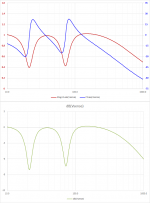
Measured voltage across the 0.22 ohm sense resistor should give a signal that looks somewhat like the mirror image of the impedance curve. With driver mounted in OEM box, the impedance has the usual double peaks surrounding the dip at port tuning frequency. Attached is the trend I measured(top plot magnitude and phase, bottom plot dB). At the impedance peaks on the SA-W2500 the sense voltage should drop to a bit less than half of what you have at the impedance dip at tuning ( ~ -8dB). You are correct that the phase should also shift around at different frequencies as you move through the peaks and dips. I’m not sure why your steady sinewave measurements are not showing this trend. The log sweep does appear to be showing the correct trend, although you need to expand the sweep range to fully show the trend. I would recommend using one of the free PC based measurement tools (REW, HOLMImpulse, etc) to get a better understanding of the frequency and phase response. It will be difficult to complete your project without this information.Plots of measurements of voltage across MFB resistor vs. input signal at various frequencies. Caveat - I am not sure about this data as I wonder if there is some crosstalk from Channel 1 to Channel 2? The signals seem too close in phase? Is this possible?...Driver mounted in OEM box.
I should have some time later today to post the step-by-step measurements for what to expect when you do start closing the loop. It should help you better understand what type of measurements will be useful along the way.
Attachments
Are you saying your feedback loop was operational (ie open loop gain > 1) all the way up to 1kHz? If so, that was quite an accomplishment. You previously mentioned using an integrator in the forward path for phase compensation. That technique works great for subwoofers, but with < 20dB feedback factors usually limits the upper bandwidth of correction to 2 – 3 octaves above woofer resonance…200Hz – 400hz. Response rolls off -6dB/octave above that point due to the integrator; a little more steeply depending on VC inductance.…I was thrilled when I finally knocked down enough gremlins to get that beautiful ruler-flat close-miked frequency response from nearly 10 Hz to nearly 1 kHz.
The always-wonderful charts and advice from bolserst tell a lot. But, the wild "classical" bass-reflex cone motion revealed in the charts still differs from even more wild acoustic output from a BR box.Measured voltage across the 0.22 ohm sense resistor should give a signal that looks somewhat like the mirror image of the impedance curve. With driver mounted in OEM box, the impedance has the usual double peaks surrounding the dip at port tuning frequency.
So linearizing the swings and managing the phases bolserst posted may do strange things to the acoustic output*.
It would be better from feedback theory to have just one swing and have it outside or nearly outside the passband. The wild phase issues are hard to deal with.
To what degree would accelerometer sensing might make things easier?
Ben
*and even wilder hard-to-guess results when you rush to sim and use a non-classical tuning
It does indeed, a 90-degree phase lag, to be specific.Doesn't an integrator result in a 90 degree phase shift? According to my knowledge of math, an integrated sinus results in a co-sinus...
That's actually a good thing for an MFB, as it makes the otherwise unusable speaker transfer function into a relatively tame (or at least, tameable) beast.
-Gnobuddy
Yes, exactly. A little above 1 KHz there was a big spike in the transfer function caused by the woofer itself, and that was the primary obstacle to extending the bandwidth any further.Are you saying your feedback loop was operational (ie open loop gain > 1) all the way up to 1kHz?
I didn't experiment with a notch filter, but looking closely at the speaker+piezo transfer function in the region of that spike, I realized that knocking down the spike height a few dB, and putting in a tiny little bit of phase lead in the critical frequency region just below it, would let me extend my servo'd response upward a bit, and actually improve the servo stability at the same time.
After some research, and writing a few Matlab scripts to simulate my findings, I found I could get what I wanted from a strategically designed Chebyshev low-pass filter with a few dB of ripple. I think it was a 2nd order filter with 2 dB of ripple, but it's been some 18 years, so my memory might be inaccurate.
I was used to thinking that low-pass filters go hand-in-hand with phase lag (not lead), so that was a bit of a surprise for me. It's the ripple in the response of these Chebyshev filters just below the cutoff frequency that does the trick.
At any rate, if I picked the parameters of the Chebyshev filter just right, it gave me a little attenuation of that nasty speaker spike, and a little bit of phase lead in the critical frequency region just below the spike. Well above the spike, it added lots of additional phase lag, of course, by by then, loop gain was below unity, so it had no adverse effect on servo stability.
With that additional tweak (Chebyshev filter as well as integrator in the forward path), I was able to increase the negative feedback of the MFB system to 18 dB at the peak (i.e. closed loop gain was 18 dB lower than open-loop gain at that frequency).
That done, the closed-loop, close-miked, acoustic frequency response (+0 dB, -3 dB) extended from 10 Hz to 1 kHz.
It's not every day you find a measurement microphone which can measure down to 10 Hz, but we had one: a Bruel and Kjaer mic that had a ruler-flat response from less than 5 Hz to well over 50 kHz (!!) Along with it's Bruel & Kjaer preamp, it cost several thousand dollars (USD), or so I was told. I'm not sure of the model number, but it might have been this one (or a close relative): https://www.bksv.com/Products/transducers/acoustic/microphones/microphone-cartridges/4954.aspx
I didn't know that! 🙂If so, that was quite an accomplishment.
It was an 8" woofer in a fairly small sealed enclosure, which probably pushed the open-loop resonance frequency a bit higher in frequency. The relatively small 8" size also pushed the first cone breakup modes higher in frequency.You previously mentioned using an integrator in the forward path for phase compensation. That technique works great for subwoofers, but with < 20dB feedback factors usually limits the upper bandwidth of correction to 2 – 3 octaves above woofer resonance…200Hz – 400hz.
Probably those two factors combined let me go about a factor of 2.5 times higher than the 400 Hz you mentioned.
My memory is that (with the integrator in the forward path), the peak in the open-loop frequency response was quite wide and gentle, transitioning into first order (6 dB/octave) rolloffs both above and below. Until that nasty spike reared it's head just above 1 kHz, at any rate.
The extra work I put into maximising gain and phase margin around the upper unith-gain frequency paid off - the closed-loop gain also transitioned very smoothly from a perfectly flat bandpass into very smooth roll-offs at both ends of the frequency response. No peaks or twitches, it looked like a textbook Butterworth band-pass response.
Unfortunately for me, there's been too much water under the bridge since I worked on this project, including a move to a new country, and several years when life was very difficult, and electronics was a very low priority. I no longer have any of my old measurements, and I can't even find the schematic of the electronics I designed and built. It was just a prototype anyway, built on a piece of proto-board.
I don't remember seeing any effect from the voice coil inductance. Open-loop response was well-behaved until that first cone breakup mode a bit above 1 kHz. After that, things got hairy rapidly, with more and more spikes appearing with every additional octave.Response rolls off -6dB/octave above that point due to the integrator; a little more steeply depending on VC inductance.
Closed loop, the integrator and Chebyshev filters worked their magic quite well, so none of those spikes above 1 kHz really showed up in the closed-loop response.
-Gnobuddy
That's what I was wondering, too. Both gain and phase are a lot more complicated than just a single 2nd order high-pass filter, which is what you get from a driver in a sealed box.The wild phase issues are hard to deal with.
I also have some concerns about things like port tuning frequency changing with air temperature (it could hot in the box, due to the heat from the voice coil).
At a quick glance, MFB with a driver in a ported box looks like it would be quite a can of worms, at least with my limited knowledge.
But in this era of servo-stabilized quad-rotor drones, and four-legged walking robots, I'm sure plenty of people have the mathematical know-how to tackle this problem, and win.
-Gnobuddy
Ported MFB does work, but you need a well damped port (read: strictly linear damping).I also have some concerns about things like port tuning frequency changing with air temperature (it could hot in the box, due to the heat from the voice coil).
At a quick glance, MFB with a driver in a ported box looks like it would be quite a can of worms, at least with my limited knowledge.
I tried this a while ago, using a very low Qes driver (RCF L12P110K, Qes=0.14) driven from a negative output impedance of about -4 Ohms (in the frequency region of interest), giving a good velocity-controlled transfer. The cone is virtually clamped by the amp and will not react to load changes. For the box this means the speaker is sort of replaced by a rigid wall and thus the Helmholtz resonator has no effective damping, resulting in a extremely high port Q, unusable. Plus the needed notch in the pre-EQ is so deep and so narrow that the slightest drift of any parameter (like you mentioned, air temperature etc) screws up the response instantly.
Good paper describing this (and my trigger for trying this by increasing apparent BL with neg impedance drive), while not using active MFB rather discussing the effect of brutally high BL... which is the same thing in the end, velocity control : Direct-Radiator Loudspeaker Systems with High-BL (google will point you to the AES paper).
Ummm, maybe an "aperiodic" port can work! Not sure if that ultimately differs much from suspensions I like that are more linear and don't have BR covert bag of resonances: slow leak or take-off-the-back or even OB. Interesting analysis.Good paper describing this (and my trigger for trying this by increasing apparent BL with neg impedance drive), while not using active MFB rather discussing the effect of brutally high BL... which is the same thing in the end, velocity control : Direct-Radiator Loudspeaker Systems with High-BL (google will point you to the AES paper).
http://www.northreadingeng.com/Vanderkooy_High_BL-prod_Drivers.pdf
Ben
Aah. Ok, gotcha. I thought there had to be more to it than a simple integrator...still an impressive accomplishment.… I found I could get what I wanted from a strategically designed Chebyshev low-pass filter…if I picked the parameters of the Chebyshev filter just right, it gave me a little attenuation of that nasty speaker spike, and a little bit of phase lead in the critical frequency region just below the spike.
 There are many ways to manipulate open loop gain/phase to extend the usable feedback range. I can usually get where I want to go sticking with building blocks of integrator, notch, and a lead or lag filter. It helps greatly if you can get the sensor and sensor mount resonance >2 octaves above the desired range. Then all you are left with is fighting any cone resonances.
Nice !!!It's not every day you find a measurement microphone which can measure down to 10 Hz, but we had one: a Bruel and Kjaer mic that had a ruler-flat response from less than 5 Hz to well over 50 kHz (!!)
Most of the measurements I post are done using a borrowed BK 4133 mike with similar specs.
It is nice to have friends with expensive toys they are willing to share 😀
Perhaps the inductance of the 8” woofer you were using was low. Most subwoofers with 2” or large VCs have inductance > 1mH which rolls off the response and adds extra phase lag exactly where you don’t want it. The Sony SA-W2500 has 2mH of inductance…you can see the effect in the first attachment of the measurements I posted back in post#211.I don't remember seeing any effect from the voice coil inductance. Open-loop response was well-behaved until that first cone breakup mode a bit above 1 kHz.
If you are thinking of applying enough feedback to make the woofer cone acceleration or velocity follow the input, then I agree. But, if you use very minor amounts of negative velocity feedback like Sony is doing(<3dB), the effect is to add damping at the impedance peaks. The same improvement could be had by using a bigger magnet to lower the Qes. If you didn’t notice, Qes= 1.6 for the Sony woofer. Perhaps Sony decided it was cheaper to add a few opamps and resistors than use a larger magnet?At a quick glance, MFB with a driver in a ported box looks like it would be quite a can of worms, at least with my limited knowledge.
There are other companies (ie Rythmik and AceBass) that use velocity and current feedback to manipulate not only the damping, but also the effective moving mass and compliance. But, this is not motional feedback in the traditional sense that you are thinking of.
See post#198.
- Home
- Loudspeakers
- Subwoofers
- Commercial motional feedback woofer available sort of