The ACH-01 is a wonderfully precise and documented device. Hard for me to believe the specs. With a buffer amp on the chip, output is low impedance. Moving cone assembly awfully heavy now a days, so weight not too bothersome. Price on eBay much less. Mine is still in the wrapper.Bentoronto -
Right now, the ACH-01 accelerometer is not on my to do list. Here are my reasons:
RE: Feeding Square waves - would I have to bypass the internal crossover in the Sony Amp?
Sure, you can put a square wave through the crossover. I don't have an intuition what it would look like coming out but, if your base freq is within the passband, should still be pretty revealing stimulus.
Ben
Surely you do. IMO, one of the pleasures of life is sharing knowledge back and forth with other people. It's also one of the pillars on which civilization was built. 🙂I was on vacation, but gnobuddy sure knows things I don't (and maybe vice versa).
-Gnobuddy
The ACH-01 proved to be too heavy when used with "normal" sized bass-units. The piezo's are easier applicable. Currently he is developing a version for VC's up to 4"... I don't know when that will hit the market.Bentoronto -
Right now, the ACH-01 accelerometer is not on my to do list. Here are my reasons:
1. Additional complexity due to ACH-01 needing a power supply.
2. Heavier than the piezo (at least compared to the piezos I have been using).
3. I think sensitivity of ACH-01 (~9 millivolts/g) is lower than the piezo's.
4. I think I recall reading (from piratelogic?) that he struggled with using the ACH-01.
5. Not that important, but cost $60 vs $2
If I am overlooking something I would be happy to reconsider testing it. I do see the phase response of ACH-01 as a function of frequency is fairly flat. However, I think the phase shift I am seeing in the above graphs is from the crossover in the Sony amp.
RE: Feeding Square waves - would I have to bypass the internal crossover in the Sony Amp?
I would be interested in knowing what folks think the advantage is of the ACH-01 vs the piezo? In my crude set up, the piezo seems to be very sensitive - the problem area are the spikes noise in my breadboard set up - and how to correct for the phase and amplitude frequency dependence - part of which I think is due to cross over in Sony amp.
Besides the things I mentioned earlier, you have to remember the end-result of a feedback system is in the image of the feedback loop. You can't reduce distortion to say, .5% and overhang to some low amount without a sensor that precise or better.I would be interested in knowing what folks think the advantage is of the ACH-01 vs the piezo?
Some manufacturers have used MF to get very good sound out of very mediocre drivers. Fair enough. But to get greatest sound out of quite good drivers (the interest of most of us here, I'd guess), you need excellent sensors.
Ben
Last edited:
I agree, Ben... To achieve that you'll need a sensor with almost perfect linearity. Adding a second transistor to the on-board amplifier of the sensor reduced the distortion of the sensor's output by a factor 10 compared to the sensor with only one FET. So in optimalization of this circuit a lot of gain is possible.But to get greatest sound out of quite good drivers (the interest of most of us here, I'd guess), you need excellent sensors.
Ben
On the other hand: What amount of distortion can we still distinguish at low frequencies?
A well designed MF system pushes distortion down to way under 1%. What do we require? 0.1%? 0.01%?
Greetz,
Edwin
What amount of distortion can we still distinguish at low frequencies?
A well designed MF system pushes distortion down to way under 1%. What do we require? 0.1%? 0.01%?
All wise.
I'd a say an issue is keeping easily heard higher error harmonics from seeping out of subs spread around the room. Doing the math, even a little output at say, 160 Hz would be much easier to hear than the fundamental at 80 Hz. And 160 Hz coming out of a sub in a back corner could upset the stereo image.
At really low freq, there is lots of distortion in cone drivers but, as you say, harder to detect.
Frankly, I think it is a wrong track to focus on MF and distortion. With subs forced to play outside their passbands (I mean they have to play across their resonant peak which is stupid engineering) and various other resonances, the main benefit of MF is cone control, with distortion second. Doesn't everybody surprised (and pleased) by the tight "fast" bass?
MF has some benefits at the extremes of cone motion. But "all bets are off" when we talk about extreme issues and MF might make matters worse too.
Ben
Last edited:
There are two major ways to use a piezo sensor.In my crude set up, the piezo seems to be very sensitive - the problem area are the spikes noise in my breadboard setup
One is to treat it as a voltage source in series with a rather small capacitance (usually only a few hundred pF). So you feed it into a very high resistance, forming a high-pass filter. Your resistance needs to be really, really, really, high, so that the -3dB frequency of the filter is at least ten times lower than your woofer resonant frequency. The extremely high resistance tends to make the circuit very susceptible to noise and interference pick-up.
The second way is to treat the piezo as a current source. If you short circuit a piezo, the (tiny) current from it rises linearly with frequency (doubles for every doubling of frequency).
You can take advantage of this by running the piezo straight to the inverting input of an op-amp configured as an integrator (feedback cap from output back to inverting input). You still need that really, really big resistor in parallel with the capacitor, to keep the op-amp input bias current from driving the output all the way to saturation as the integration capacitor charges up. You also need a JFET-input op-amp, so that input bias current is really low.
Since you have negative feedback via that integration capacitor, the inverting input of the op-amp is a virtual ground. Running the piezo straight to this ground effectively shorts it out - but the piezo output current goes through the integration cap, so you get your piezo sensor output voltage on the opamp's output pin.
Using this method gives you much better noise immunity. The virtual short-circuit across the piezo makes it much less prone to picking up electrostatic interference.
This second method is sometimes called a "charge mode amplifier", since the integration capacitor collects the electric charge generated by the piezo when it is deformed.
You can find a little more information about charge mode amplifiers for piezo sensors in section 3.2 of this Texas Instruments PDF : http://www.ti.com/lit/an/sloa033a/sloa033a.pdf
-Gnobuddy
Gnobuddy - Thank you, Sir, for sharing your valuable knowledge!
Here are my near term objectives for this Sony W2500 project:
1. So far, I have compared the input signal (from ipod to amp) to the piezo output noting frequency dependent phase and amplitude, but I think a better approach would be to look at the signal coming out of the output of the op-amp (IC104 reference to Sony SA-w2500 Schematic Diagram Input control board). If I understand correctly, this is the signal that would be compared to the output of the piezo (after some processing). I have identified the IC104 op amp but not sure which pin is the output but can probably figure it out once I find the specs sheet on it (IC104 is NMJ4565D). I don't know if I can access that pin to get a probe on it though...may have to try to solder a hair thin conductor on pin 1? to bring the signal up away from the board so I can get a probe on it.
2. I would like to do a comparison of the piezo output signal with and without the native built in MFB. I am not sure how this can be safely done without damaging the amp...short out feedback resistor? But that doesn't make sense to me as I would think doing this (shorting out the resistor) would cause the amp to think it needs to put out max power to try to get the speaker to move as a shorted MFB resistor implies no woofer movement?
3. Get some voltage readings across that feedback resistor (R519) as a function of frequency / amplitude.
4. Work on my noisy op-amp circuit.
Crazy thought....what if one could judiciously match the piezo output to the voltage difference across the feedback resistor R519 and just pipe it (instead of that from R519) to IC202 and use the existing 4 MFB- associated op amps in the Sony circuit ? At first glance, this sub circuit of op amp look like they have much of what is needed already in place. Could 20 Hz for $0.20 be in the horizon ?
Last edited:
Ok, now for the promised levity…measurements of the Sony SA-W2500 “subwoofer”
Attachment #1: Here is measurements of port, piston, & summation made straight from the test computer, no EQ, no MFB, just woofer + box response.QUOTE]
May I inquire how you measured the response without MFB - curcuit mid?
I did it a number of different ways. The easiest is to solder a temporary short across C201. This grounds the input of the buffer stage for the MFB signal, effectively removing all the feedback signal reaching the opamp that subtracts it from the preamp signal.… how you measured the response without MFB - curcuit mid?
Be aware that the preamp includes an underdamped HP filter built around IC103(2/2) which adds a +6dB EQ boost around 40Hz and rolls off -12dB/oct below that. If you plan to use the SONY electronics module for an accelerometer based MFB system, you will want to fix that. If you remove R125 (5.6K surface mount resistor) you will remove the boost, and have a flat response down to a -3dB point of about 16Hz. Also, you will want to transplant the woofer into a sealed enclosure or effectively seal or block the port.
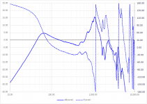
Looks like you have been getting some good information from Gnobuddy concerning the use of piezos as accelerometers. I would recommend as a near term goal, to measure the open loop response of the woofer/piezo system. Attached is an example of the type of measurement you need so that you can decide if your sensor is good enough as far as low frequency phase margin, and high frequency resonance. I know the dust cap feels sturdy, but there will likely be a mechanical resonance in the 1kHz – 2kHz range similar to what is shown in the attachment. If you don’t want to remove the dust cap and work out a more rigid attachment method between the VC and sensor, you will need to use a notch filter to remove the peak to avoid oscillation. Once removed, you should be able to get 15dB or so of feedback even with a peak as low as 1kHz. If I have time tomorrow, I will post a few more plots showing the steps to take as far as removing the peak, adding an integrator to give you the phase margin you need for closing the loop and, and the resulting response as feedback factor is increased.
Back in post#414 when you were looking at woofer response to a 36Hz sine wave, was this still in the OEM ported box? If so, the woofer motion would be reduced by the port resonance. If you are wanting to see the distortion that results from VC motion as it approaches Xmax, you will need to seal the port, or just remove the woofer from the box. Then with 25Hz – 35Hz signal, increase the volume till woofer motion is > 0.5”…you will see plenty of distortion.
Attachments
IMO, the "Piezo accelerometer substitute for back EMF in Sony W2500" discussion is drifting out of thread.
The Sony W2500 deserves this present discussion on diyAudio because it bases on the Servo-Sound principle (closed box having a back-EMF estimate feedback), this time applied to a ported box.
Now look the Sony W2500 power amplifier. It exhibits a plain normal voltage gain. The beauty is there. There is no "open loop" voltage gain boost.
The importance of the Sony W2500, is that it shows that it suffices to add to a conventional power amplifier + ported speaker combination, a modest proportion of back-EMF estimate as global (outer) feedback loop, actually acting as positive membrane speed feedback (you may actually say that the voltage gain has increased somewhere), for attaining a linear frequency response extending down 30 Hz.
The Sony W2500 is thus not a "speed-follower" combination, that's made of a very high voltage gain power amplifier closed-loop driven by a cone speed estimator, or preferably a cone acceleration estimator (speed first derivative).
Tadeusz Korn, who was the "Servo-Sound" company founder and technical director, said that the reliability and stability of his active boxes (SL15, SL20) resulted from the fact that they were not "speed-followers" derivatives nor "acceleration followers" derivatives, but instead, active boxes having a normal power amplifier inside (normal voltage gain), however assisted by a modest feedback loop (between 12 dB and 15 dB he said once), originating from some "black box". Such "black box" got described in his US3647969 patent filed in 1969. Reading such patent, it is obvious that the "black box" role, is to elaborate a membrane speed estimate relying on a Voight bridge, thus requiring a difference amplifier. In the Servo-Sound implementation, such difference amplifier consists on a single transistor having both the base and emitter used as inputs, and the collector used as output. Quite funny, you can see such transistor on the circuit board of the first SL15 batch that went on the market as soon as 1968, which predates the patent filing. Later on, inside the SL20, T.S. Korn managed to put such transistor along some other components, into a small "black box" filled with epoxy resin, creating some buzz about the actual schematic, for those privileged ones not having an early SL15 box at disposition.
Call it effortless feedback if you want. All this may look confusing for a non-specialist. Make a mental memo for yourself. Notice there exist since 48 years an easy and effective way to improve a plain normal active box fitted with a plain normal power amplifier, by adding a modest 12 dB to 15 dB positive feedback, based on membrane speed (thus not membrane acceleration), up to 300 Hz or so, and this applies to a closed box (Servo-Sound SL15 and SL20 series, 3A Andante series), to a passive radiator box (Korn & Macway KM30 and KM50 series), and to a ported box (Sony W2500).
The Sony W2500 deserves this present discussion on diyAudio because it bases on the Servo-Sound principle (closed box having a back-EMF estimate feedback), this time applied to a ported box.
Now look the Sony W2500 power amplifier. It exhibits a plain normal voltage gain. The beauty is there. There is no "open loop" voltage gain boost.
The importance of the Sony W2500, is that it shows that it suffices to add to a conventional power amplifier + ported speaker combination, a modest proportion of back-EMF estimate as global (outer) feedback loop, actually acting as positive membrane speed feedback (you may actually say that the voltage gain has increased somewhere), for attaining a linear frequency response extending down 30 Hz.
The Sony W2500 is thus not a "speed-follower" combination, that's made of a very high voltage gain power amplifier closed-loop driven by a cone speed estimator, or preferably a cone acceleration estimator (speed first derivative).
In a "speed-follower" combination, the feedback is originating from a cone speed estimator, and thus, a + 6 dB / octave frequency response curve results.
You thus need an integrator as pre-equalizer.
In case you don't like the complication of adding a pre-equalizer, you can pass the feedback signal into a differentiator (first derivative) for transforming the speed feedback signal into an acceleration feedback signal.
In case the feedback is originating from a cone acceleration estimator (a piezo disc used as very high impedance voltage source), a horizontal frequency response curve naturally results.
Anyway, as the above approaches both rely on a very high open loop gain, and a very strong feedback, the stability gets problematic as soon as the cone speed or cone acceleration estimator is not accurate.
Therefore in real life, you only can materialize "degenerated speed-followers" or "degenerated acceleration-followers" having their feedback path fitted with a lowpass filter, reducing the frequency bandwidth of the feedback signal. Usually, you would set the -3 dB point to 300 Hz or so, I mean the frequency where the velocity feedback or acceleration feedback magnitude has dropped so much, that it becomes same as the local power amplifier voltage feedback magnitude. This guarantees stability past 300 Hz. And, for not ending up with a global frequency response exhibiting a 6 dB / octave rise past 300 Hz, you need to reduce the power amplifier gain past 300 Hz, as well. And because of the phase lags introduced by both lowpass filters, the stability improvement is not going to be as high as expected. As you can see, "degenerated speed-followers" and "degenerated acceleration-followers" are tricky, full of compromises, and this is the reason why the industry has not popularized them.
Tadeusz Korn, who was the "Servo-Sound" company founder and technical director, said that the reliability and stability of his active boxes (SL15, SL20) resulted from the fact that they were not "speed-followers" derivatives nor "acceleration followers" derivatives, but instead, active boxes having a normal power amplifier inside (normal voltage gain), however assisted by a modest feedback loop (between 12 dB and 15 dB he said once), originating from some "black box". Such "black box" got described in his US3647969 patent filed in 1969. Reading such patent, it is obvious that the "black box" role, is to elaborate a membrane speed estimate relying on a Voight bridge, thus requiring a difference amplifier. In the Servo-Sound implementation, such difference amplifier consists on a single transistor having both the base and emitter used as inputs, and the collector used as output. Quite funny, you can see such transistor on the circuit board of the first SL15 batch that went on the market as soon as 1968, which predates the patent filing. Later on, inside the SL20, T.S. Korn managed to put such transistor along some other components, into a small "black box" filled with epoxy resin, creating some buzz about the actual schematic, for those privileged ones not having an early SL15 box at disposition.
Call it effortless feedback if you want. All this may look confusing for a non-specialist. Make a mental memo for yourself. Notice there exist since 48 years an easy and effective way to improve a plain normal active box fitted with a plain normal power amplifier, by adding a modest 12 dB to 15 dB positive feedback, based on membrane speed (thus not membrane acceleration), up to 300 Hz or so, and this applies to a closed box (Servo-Sound SL15 and SL20 series, 3A Andante series), to a passive radiator box (Korn & Macway KM30 and KM50 series), and to a ported box (Sony W2500).
Perhaps there is some misunderstanding of terminology here. In all negative feedback systems, the closed-loop gain is less than the open-loop gain. This applies to every kind of negative feedback, and doesn't matter how the feedback signal is derived.Now look the Sony W2500 power amplifier. It exhibits a plain normal voltage gain. The beauty is there. There is no "open loop" voltage gain boost.
I'm not sure how to interpret "voltage gain boost" - but if you were to open the negative feedback loop in any kind of negative feedback system, you will experience a boost in gain, as the system moves from the (lower) closed-loop gain to the higher open loop gain.
Personally, I find the term "speed-follower" quite unhelpful, since it has no well-defined technical meaning, and therefore doesn't clarify any concepts.In a "speed-follower" combination
The slowest element in an MFB system is the speaker itself; the voice coil can generate a maximum acceleration of (BL)*Imax/m , where BL is the woofer motor's BL product, Imax is the maximum voice coil current, and "m" is the moving mass of the coil, cone, and part of the surround.
As we saw in a previous post, this maximum acceleration tends to be of the order of a few tens of g's. That's fast for a fragile speaker diaphragm, but incredibly, unbelievably slow compared to any audio amplifier.
Not really. The amount of negative feedback is entirely up to the designer, and can vary from no feedback to, say, 20 dB of feedback.the above approaches both rely on a very high open loop gain, and a very strong feedback,
Very small amounts of negative feedback (a few dB, say) are of very limited usefulness; they provide only slight improvements in performance at best.
If the sensor is inaccurate, negative feedback can worsen performance, rather than improve it. Very true.the stability gets problematic as soon as the cone speed or cone acceleration estimator is not accurate.
I don't think the accuracy of the sensor has much to do with stability, though, unless we're talking about mechanical resonances in a poorly designed piezo sensor or something like that.
A low-pass filter in the feedback network will try to create the inverse behaviour - a treble boost, or differentiator - in the entire system. This is not only unwanted, but also a recipe for instability. 😕...having their feedback path fitted with a lowpass filter
I used a flat-frequency Alesis RA-100 power amplifier, which was flat out to a few tens of kHz, well above the audio band.
Closed-loop, and close-miked, the MFB speaker frequency response was almost ruler-flat from 10 Hz to about 1 kHz.
As usual, room-speaker interaction would have it's way with the speaker, and that ruler-flat response only exists when your ear (or measurement mic) is right up against the speaker cone.
It was only an 8" driver, so maximum SPL at 20 Hz would surely have been utterly useless, too little to hear. That ruler-flat response, though, also indicates a very crisp transient response.
What do you mean by "stability improvements"? 😕 Do you mean "performance improvements" of the speaker?And because of the phase lags introduced by both lowpass filters, the stability improvement is not going to be as high as expected.
In my case, I ended up with a ruler-flat (close-miked) frequency response from 10 Hz to 1kHz. I also saw THD (distortion) drop by 18 dB at some frequencies. That is a nearly ten-fold reduction in (mostly 3rd harmonic) distortion from the woofer, folks!
The ear is not very sensitive to anything at very low frequencies, and that includes distortion. Nevertheless, the speaker did sound "crisper" or "tighter" on most program material. Often "tighter" means simply that deep bass has been sacrificed - but that was not the case here.
The upper frequency limit - 1 kHz - came from cone breakup modes in the specific 8" woofer we were using. The MFB woofer was intended to be part of a 3-way speaker system, where its top-end would be restricted to well below 1 kHz .
All of these sound like marketing terms, with no well-defined technical meaning. In my opinion, they only confuse the issue, and are best avoided. It's like saying "my car has effortless acceleration", or "effortless rear-wheel drive", or "effortless front-wheel drive" - it doesn't actually convey anything. A graph of standing-start speed vs time, however, would convey everything, no words needed...."degenerated speed-followers"
..."degenerated acceleration-followers"
..."speed-followers"
..."acceleration followers"
..."effortless feedback"
In the same way, the actual performance of a servo is described in mathematical terms, by the transfer functions of the amplifier, speaker/piezo system, and feedback system. That's it - and it doesn't matter what you call it!
I'm sure you meant negative feedback, yes?...by adding a modest 12 dB to 15 dB positive feedback, based on membrane speed (thus not membrane acceleration),
Small amounts of NFB may be better than nothing, but more is better, as long as the servo system is properly designed for stable performance under all operating conditions. I aimed for 20 dB in the system I designed and built, but ended up with about 18 dB of feedback; it would have taken a lot more complexity to get those last 2 dB, so I didn't bother.
On the cone velocity vs. cone acceleration issue: as I noted earlier, an acceleration sensor needs to be fed through an integrator to get the phase relationships correct for loop stability. Guess what you get when you integrate acceleration? Yup, velocity! 😀
So there is pretty much no difference in MFB performance whether you start with a velocity sensor, or an acceleration sensor. The only difference is you must add an integrator if you use acceleration-based feedback.
-Gnobuddy
An exceedingly helpful post ending with a fundamental truth.So there is pretty much no difference in MFB performance whether you start with a velocity sensor, or an acceleration sensor. The only difference is you must add an integrator if you use acceleration-based feedback.
I'm now rather forgetful about basic driver theory, but don't drivers produce sound levels related to cone velocity below a certain freq (related to their diameter or radiation resistance or wavelength), and to acceleration above?
If you are using an acceleration sensor to convert the driver to a constant accelerator, would it be best to introduce the circuitry to restore a driver to constant velocity behaviour within the feedback loop or as suitably shaped EQ external to the amp?
Ben
@ Gnobuddy : your comments in post #433 indicate that you have no understanding of the Sony W2500 schematic, as given in post #402.
@ Gnobuddy : you know enough about electronics, loudspeakers and feedback systems for giving lessons to others on diyAudio. Unfortunately, as side effect, it looks like you are somewhat squatting this present discussion, that I consider to be dedicated to the Sony W2500. I must say, the situation would be less confusing if this present discussion title had the words "Sony W2500" inside. I must also say that this present discussion title has the word "commercial" inside. Thus, and especially in case the particular feedback system that you are describing is not "commercial", I strongly suggest that you re-establish the description of it, inside a proper & dedicated & documented (schematics and pictures please) discussion.
@ Gnobuddy : you appear to ignore the fundamentals of a "speed-follower" setup. Such terminology dates back from the invention of the moving coil speaker. As soon as the moving coil speaker got invented, some wanted to extract and exploit the "motional voltage" generated following the Lenz-Faraday law, appearing at the terminals of the moving coil, hence appearing as a supplement to the (Rcoil + Lcoil) * current. Following the Lenz-Faraday law, such "motional voltage" is directly proportional to the instantaneous coil speed. In order to extract such "motional voltage", came the Wheatstone bridge method (requiring a coil), then came the Voight bridge method (requiring a capacitor). The Voight bridge was (and is still) the preferred method. The Sony W2500 schematic reflects some inspiration from the Voight bridge, through C209. Much later after the invention of the moving coil speaker, came Prof. W. Marshall Leach, Jr. establishing the exact nature of the moving coil, as affected by eddy currents (also called Foucault currents) circulating inside the iron core, battling against the cause of the motion, thus somewhat decreasing the voltage at the coil terminal, quite noticeable when the frequency is rising. This is why the actual speaker impedance module rise from 1 kHz to 10 kHz, is always less than you would expect from the measured coil inductance at 1 kHz. The Sony W2500 schematic reflects some inspiration from Prof. W. Marshall Leach, Jr. theory, through R210. Anyway, at some stage, people was in the hope that, provided the motional voltage extraction was perfect, one could connect a loudspeaker to a high gain power amplifier (say a voltage gain of 70 dB instead of the usual 30 dB), and establish a 40 dB negative feedback loop, for imposing the coil speed. This is such setup, that got named "speed follower". Unfortunately, because of the human sound intensity perception being proportional to the speaker cone acceleration, instead of the speaker cone speed, a speed-follower exhibits a frequency response curve plagued by a +6 dB per octave slope. As I already wrote in my previous post, in order to restore an horizontal frequency response curve, you can install an integrator as pre-equalizer, or you can differentiate the feedback signal. Not a big issue. Anyway, and unfortunately, a 40 dB feedback as sketched above for materializing a "speed-follower" can not be reached in practice, unless you can predict with less than 1% error (or realtime measure) the DC resistance of the moving coil (that's varying with temperature), and unless you can predict (or realtime measure) with less than 1% error the exact nature of the impedance of the moving coil, embedding some normal inductance, and also embedding some impedance reduction caused by the eddy currents. I'm telling this, because with a 40 dB feedback (factor of 100), you need to consider your feedback signal that's plagued with a 1% error, positive or negative, that gets multiplied by the factor 100 of the 40 dB extra-open loop amplification. Thus, in case you are not lucky, if the error puts you into the negative domain, your supposedly negative feedback, becomes a positive feedback, ruining the stability. And, in case the 1% error is on the positive side, you will end up with a feedback that's twice the wanted one, reducing the output by 6 dB. At the end of the day, you get forced to implement a "degenerated speed-follower", basing on something between 12 dB to 15 dB motional voltage feedback, instead of the 40 dB motional voltage feedback. This, because still in 2016, you cannot avoid a 5% inaccuracy of the coil DC resistance prediction caused by temperature variations, along with a 5% inaccuracy of the coil AC impedance caused by the difficulty to take the eddy currents into account.
This being said, in case you organize the feedback, basing on a piezo sensor (acceleration sensor), or basing on an electret microphone, that's a completely different story, completely departing from the Sony W2500 case study.
In case you organize the feedback, basing on a piezo sensor (acceleration sensor), or basing on an electret microphone in the 10 Hz to 100 Hz frequency band, you may attain a feedback of 20 dB or so without ending up in stability issues, ironing out distorsion in a spectacular way between 10 Hz and 100 Hz, and flattening the response curve so it fits in a 2 dB corridor between 30 Hz and 100 Hz. Been there, done this. The major issue with such approach, is the mechanical coupling. In case the mechanical coupling is good, you may extend the 20 dB feedback domain, from 100 Hz to 300 Hz. I mean, still 17 dB of feedback at 300 Hz, and no feedback at all past 3 kHz (in case you gradually mute the feedback using a 1st-order lowpass filter having a corner frequency of 300 Hz). This is reachable, by rigidly attaching (hard glue) a rigid metal bracing atop the voice coil former (do not rely on the dust cap, thus), on which you rigidly attach a 5 mm diameter piezo disc, not allowing it to flex (avoid flexion modes below 3 kHz), that's loaded by a small mass (an epoxy glue drop) whose inertia is generating the back and forth pressure, and whose (quite high) viscosity is damping the unwanted high frequency flexion modes past 3 kHz. You also need to pray, for the whole assembly resisting the vibrations, and temperature variations. You need to design this, in such a way that the rigid bracing doesn't impede the Xmax and doesn't impede the polar pieces ventilation.
Please note, because of progressively muting the acceleration feedback signal past 300 Hz, you may need a pre-equalizer, or you may need to precisely shape the frequency response of your power amplifier. Or both.
Inside the Philips MFB boxes (532MFB, 541MFB, 544MFB, 545MFB, etc..) the piezo element is a small square piece sitting inside a silicon rubber carrier, designed to damp most flexion modes in a conservative way. As consequence, the Philips MFB system imposes a weird (mechanical) lowpass filter on the feedback signal, reducing the effective feedback to almost nothing past 300 Hz. After so many years, the silicon rubber carrier may be split (mechanical damage causing play), or may be cooked (not anymore the required viscosity). The situation is different with the Philips F9638 MFB boxes (flat membrane, they are the last generation Philips MFB) where the acceleration sensor is a plain normal piezo disc glued on his center, on a conical carrier made of paper, sitting atop the coil former.
Velodyne shows a different approach in their United States Patents US4573189 and US4727584, where the piezo element is a 1 millimeter beam (very low output, that's bad) exhibiting an ultrasonic resonance frequency (that's good) directly connecting to a "charge amplifier", both mounted within the voice coil former upper section thickness. This way, the devices cannot impede the Xmax, and the polar poles ventilation. The "charge amplifier" wording suggests that Velodyne is exploiting the piezo element current (in a context of very low input impedance), instead of the piezo element voltage (in a context of very high input impedance). Such "very low impedance current mode" choice may be justified by the very low output one can expect from such a small sensor.
For you and the people following this present discussion, I need to clarify the following crucial points about the Sony W2500.
According to the Sony W2500 schematic, as given in post #402, the power amplifier voltage gain is normal, nominal, as defined by R712 (47 K) and R704 (1.5 K). Voltage amplification is approx 32. Voltage gain is approx 30 dB. We are thus not facing a boosted-gain power amplifier, that gets dimmed by some external, global negative feedback.
There is an external, global feedback, consisting of two signal branches converging to an opamp wired as difference amplifier (x202b).
The "V" branch picks up the power amplifier output voltage (R214), enters the non-inverting input of the difference amplifier, passes through the x201a and x201b buffers, and enters the inverting input of x202a that's the feedback mixer, actually mixing the feedback signal with the audio input signal. The "V" branch materializes thus an external, global negative feedback.
The "I" branch picks up the loudspeaker coil current (R519), enters the inverting input of the difference amplifier, passes through the x201a and x201b buffers, and enters the inverting input of x202a that's the feedback mixer, actually mixing the feedback signal with the audio input signal. The "I" branch materializes thus an external, global positive feedback.
The "V" and "I" branches that are consisting of a 0 dB gain voltage difference amp (x202b), two buffers (x201a, x201b), and a mixer (x202a having R202 and R204 as gain-defining resistors), provide an almost 0 dB voltage gain.
This is the remarkable specificity of the Sony W2500 schematic, and it gets even more remarkable, knowing that the Sony W2500 is a ported box, not a closed box.
Flattening the frequency response curve of a loudspeaker this way, between 30 Hz and 300 Hz, appears thus as a triple miracle : 1) there is no high open-loop gain, 2) the "negative V" and "positive I" feedback branches exhibit an almost 0 dB gain, and 3) this is a ported box.
Last edited:
And I remain grateful to bentoronto for his finding, I mean the Sony SA-W2500. There is a lot to learn, from such design.
I have learned a tremendous amount reading the last several enlightening posts (and this entire thread) and want to thank GnoBuddy, bolserst, steph_tsf and bentoronto and others for their gracious contributions of their knowledge, experience, time and effort in posting - greatly appreciated!
I am trying to figure out a non-destructive way to probe the output of the signal coming out of IC104 op amp (that would be compared to the output of the piezo) to get an idea of phase and amplitude rather than comparing the frequency generator output to the piezo output as I have previously shown. This is because there is a band pass and other caps in the preamp pathway to IC104 which must be shifting the phase. But the IC104 output pin (similar to all the other solder joints on the board) are tiny! I don't want to bust out the solder gun yet - any tricks to probing such small points on the board?
Maybe tonight, I can see if I can at least get a read across the 0.22 Ohm MFB resistor just to see what's going on there.
I have a question for GnoBuddy if you don't mind me asking - what happened after you succeeded in creating you MFB system? That must have been an exhilarating feeling. You mentioned the 8" woofer you applied MFB to was too small so why not scale up to a couple of 12" woofers? It seems like once you had a working system, and one working so well, the temptation would have been to do more / home installation in the walls...something?
In thinking of what will be needed to pipe the piezo output into the Sony W2500 preamp circuit - one (of myriad) things I am confused with - what is the difference between an op amp integrator circuit (see attached on example) and an active Low Pass Filter? They look similar to me.

First readings: Voltage across Sony W2500 0.22 Ohm MFB Resistor at Various Frequencies
Proud of myself here...managed to get a probe on the MFB resistor without shorting things out and get some measurements. I kept amplitude from frequency generator fixed (low volume) and took snapshots of the waveform at 30, 45, 60 and 90 Hz. The frequency indicated on the scope snapshots is in excellent agreement with what I was feeding into the subwoofer preamp. Note amplitude dependence as a function of frequency.
Fig. 1. 30 Hz

Fig. 2. 45 Hz

Fig. 3. 60 Hz

Fig. 4. 90 Hz

Proud of myself here...managed to get a probe on the MFB resistor without shorting things out and get some measurements. I kept amplitude from frequency generator fixed (low volume) and took snapshots of the waveform at 30, 45, 60 and 90 Hz. The frequency indicated on the scope snapshots is in excellent agreement with what I was feeding into the subwoofer preamp. Note amplitude dependence as a function of frequency.
Fig. 1. 30 Hz
Fig. 2. 45 Hz
Fig. 3. 60 Hz
Fig. 4. 90 Hz
Last edited:
- Home
- Loudspeakers
- Subwoofers
- Commercial motional feedback woofer available sort of