Indeed, most people associate FIR filters to phase linear filters, plagued by delay. In reality, a FIR filter can be minimum-phase just like an analog filter. And like you said, a FIR filter connecting to the analog feedback signal (accelerometer, or electret microphone) has the advantage of being easily modified in real time. Especially when it is self-adaptive, governed by the Widrow-Hoff converging algorithm, or governed by some other algorithm converging to the optimal system stability. But wait a minute. What about the ADC and DAC conversion time? The more the delay, the more the risk of instability. 16-bit ADCs and 16-bit DACs operating at 48 kHz (preferably 96 kHz), featuring a 90 dB dynamic range, featuring the required anti-aliasing and reconstruction filters, and also featuring a zero delay conversion, are not common. Which ones would you advise?If digital filters are to used then they must be of the IIR type, mimicking analog functions or be analog from the beginning. I guess Meyer used digital filtering in the prototype phase because one can do changes more easily.
Many thanks for your careful explanations. Appreciated.
But if the ANIC FET provides protection, wouldn't you get odd results when you disconnect the feedback when the FET conducts? Perhaps no problem if the ANIC handles only positive current and a secondary voice coil is handling negative feedback?
I'm unconvinced copper heating is an issue in houses; moreover, it must have a time constant that is really hard to model, intriguing as that idea is.
Ben
Not at all. As soon as the FET conducts, you resume in "normal" mode like a grand pa speaker enclosure.But if the ANIC FET provides protection, wouldn't you get odd results when you disconnect the feedback when the FET conducts? Perhaps no problem if the ANIC handles only positive current and a secondary voice coil is handling negative feedback?
Yes indeed, for home audio that would be overkill, but you know what kids are capable of when the parents are not there. And, like you wrote, predicting the voice coil temperature is complicated matter, especially when the pole piece is vented.I'm unconvinced copper heating is an issue in houses; moreover, it must have a time constant that is really hard to model, intriguing as that idea is.
16-bit ADCs and 16-bit DACs operating at 48 kHz (preferably 96 kHz), featuring a 90 dB dynamic range, featuring the required anti-aliasing and reconstruction filters, and also featuring a zero delay conversion, are not common. Which ones would you advise?
Apart from prototyping I wouldn't use DSP at all for this task. And for a prototype I doubt whether the AD/DA must be 24 bit delta-sigma.
If memory serves me right the Meyer monitor achieves around 1% THD at 120 dB SPL. With modern high-quality drivers one can get quite close without using any feedback for damn loud home playback. Just have a look at the driver in the JBL M2.
OTOH when used for exorbitantly high levels, like they are needed in sound reinforcement (where the Powersoft solution is targeted at), I don't doubt that it will help in achieving a good balance of reliability, performance and price.
Regards
Charles
T/S parameters are data extracted from a system, a measurement system, i.e. a electrical closed circuit. They do not exist on their own. The parameters of the data sheet are given for a pure voltage source but it is easy to predict what the response around the resonance will be with a different source impedance.Truly helpful discussion to re-think MF in terms of "system T/S" rather than "driver T/S", as bolserst started earlier.
Thanks for the schematics. I thought of something similar for a transform applied to a closed box with an extension to very low frequencies.
Not at all. As soon as the FET conducts, you resume in "normal" mode like a grand pa speaker enclosure.
But when you change the feedback by say, 10 dB under certain conditions, the loudness changes by 10 dB???
B.
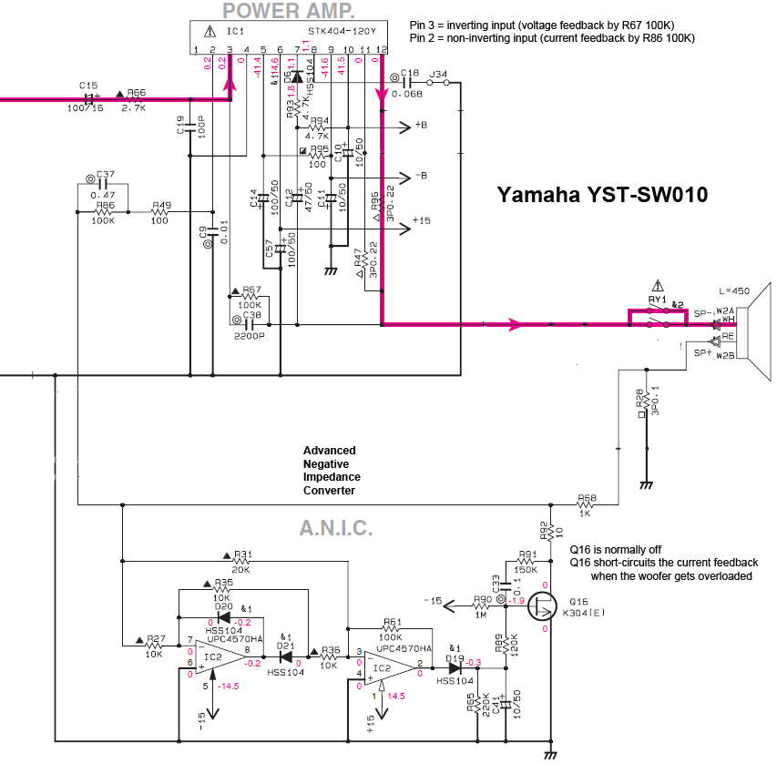
The Yamaha does use positive current feedback to modify the amplifier output impedance.There is a lot of confusion here. Just obey the facts. Sony applies voltage feedback (just as normal) and also current feedback (the 0.22 ohm resistor voltage drop processed by an op-amp). Same as the Yamaha YST-series subwoofers. Such current feedback is a positive feedback. The more output current, the more output voltage. As consequence, the power amplifier emulates a negative output impedance, say - 2.5 ohm. Such negative impedance comes in series with the voice coil copper resistance, say + 3.5 ohm. The system behaves like there is a woofer having a 1.0 ohm copper resistance. The woofer electric damping has thus significantly improved in the low frequencies. This is a significant Thiele-Small parameter change (should I write optimization).
However, if you trace the circuit for the Sony, you will find that it is not using positive current feedback.
Sony is using a bridge circuit to extract the back-EMF signal and provide velocity feedback.
Attachments
Sony is using a bridge circuit to extract the back-EMF signal and provide velocity feedback.
Yes, and includes compensation for VC inductance.
I wonder what the implied inductance across the bridge would be? And how that compares to reality? (And if it matters much?)
Ben
About "system Q", always seems peculiar to aim for anything but the lowest Q. Certainly there is no "critical" Q that speaker builders should aim for as a goal; and despite the magic of calling it "critical", in reproduction, deader is better.*
Ben
*and that's because a speaker should have no voice (timbre) of its own
System q, or qtc, simply refers to the response at the low knee and the roll off below the low knee. If your qtc curve is the inverse of the room gain curve so that they sum to flat, that's about as good as it's going to get. So there is a specific q that a speaker designer can shoot for as a very wise goal.
You have stated a few times that you prefer a bump in response near the bottom of the speaker's passband since you don't like a flat response. By definition, that is a VERY high q response (the opposite of the lowest possible q), you are creating a situation where the speaker has it's own voice.
Once again you contradict yourself when explaining what you actually like vs your whimsical flight of fancy descriptions of how you think things should be.
I'm unconvinced copper heating is an issue in houses; moreover, it must have a time constant that is really hard to model, intriguing as that idea is.
Ben
So you've never heard of speakers being blown from overpowering? This is an extremely common issue in domestic usage, since most people go for the smallest possible speakers available, speakers that are ill equipped to deal with the spl level that the customers desire.
Long before a speaker physically stops working due to thermal overload the voice coil heats up, t/s parameters change, frequency response changes, everything changes. This usually starts to happen at about 1/4 of the speaker's rated power handling and gets worse with increased power and extended time.
You might not personally have experienced this issue much because all your subwoofers use antique drivers with ~2 mm xmax, so they reach excursion limits before thermal limits, but it is a very real problem for people with more modern speakers.
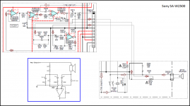
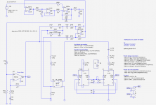
I looked at the Sony service manual. Attached is a simplified circuit diagram. I agree on your bridge feedback idea exploiting the current in one arm, and the voltage in the other arm. I disagree with you about the current feedback. I still think that the instantaneous current measurement serves as positive feedback.The Yamaha does use positive current feedback to modify the amplifier output impedance. However, if you trace the circuit for the Sony, you will find that it is not using positive current feedback. Sony is using a bridge circuit to extract the back-EMF signal and provide velocity feedback.
In order not to create a ground loop, Sony relies on a differential amp having four 220K resistors for measuring the voltage drop on the current sensor (R519 0.22 ohm). Such differential amp gets slightly out of balance because of the two 12K resistors in series in the positive branch.
A closer examination reveals that the positive branch of the differential amp gets corrupt by the injection of the voltage feedback materialized by R209 having a value of 1K. Indeed, the "- curr (blue)" signal gets attenuated by a factor of 25 prior entering the differential amp. While at the same time, the "+ curr (red)" signal enters the differential amp without being attenuated. This is unorthodox, and far from academic. One should verify the printed circuit boards tracks, for determining if the circuit diagram duly reflects the circuit board tracks.
There is a problem with CNP103 and CN601 connecting the two boards. Their wiring is tricky. The CNP103 pins don't match the CN601 pins. Can somebody take a picture of the wiring ?
For sure, the "volt (green)" signal is working as negative feedback.
I say this because it enters the positive side of the differential amp (R209 1K), then goes through the two buffer op-amps in series, then enters the mixer op-amp which is low gain inverting, then enters the power amplifier which is non-inverting (amplification factor defined by R712 and R704).
Consequently there is a high probability that the current arm of the bridge is working as positive feedback. I have thus connected CN601 pin 8 to CN103 pin 4, and CN601 pin 9 to CN103 pin 2. This way, the "+ curr (red)" signal enters the inverting input of the diff amp, then goes through the two buffer op-amps in series, then enters the mixer op-amp which is low gain inverting, then enters the power amplifier which is non-inverting (amplification factor defined by R712 and R704). As there are two inversions, this is indeed positive feedback. My hypothesis, thus.
I remain highly perplex.
We should simulate this using LTspice.
Attachments
The conclusion of my former post is that Sony is faking a differential measurement of R519 (0.22 ohm) voltage drop. As consequence, as soon as there is a voltage difference between the power ground and the signal ground, such voltage difference will corrupt the current feedback signal. Fortunately, it is the "+ curr (red)" signal that's entering the "differential amp", without being attenuated. The current feedback is thus there, however of poor quality because of being not immune from ground noise.
Imagine now, my hypothesis about the "+ curr (red)" and "- curr (blue)" signals to be wrong. That would mean that the ""+ curr (red)" signal gets attenuated by a factor of 25 prior entering the "differential amp". That would mean also, that it is the "- curr (blue)" signal, that's entering the "differential amp", unattenuated. And such signal is the power ground potential. Which then means that there is no current feedback at all. You promote ground noise, that's all.
I found another glitch. You may have noticed it, there is a kind of nonsense with R209 (1K) having in parallel (R210 (22k) + C204 (100nF)). Is the Sony implementation so critical, that it is required to wire a frequency compensation network, that's providing a frequency-dependent correction of less than 0.4 dB?
The bridge component values used compensate for ~0.6mH of VC inductance.Yes, and includes compensation for VC inductance.
I wonder what the implied inductance across the bridge would be? And how that compares to reality?
Since the actual VC inductance = 2mH, I had previously stated that this was poor/partial compensation.
Note that the bridge is not well balanced either. You need to increase the upper resistor arm from 24K to about 30K, or reduce the lower arm from 1K to 800 ohm. I briefly soldered a 4.7K resistor across the 1k to verify that balance improved. At first I thought the resistor values were chosen to set a compromise that would improve balance when the VC heated up. But, the imbalance is in the wrong direction. Any increase in VC resistance pushes the bridge even further out of balance.
I guess it depends how you want to think about it. If you want to think about the positive and negative feedback paths in isolation and then sum to get the combined effect, that is fine. The negative feedback definitely dominates with a bridge circuit even if the bridge is out of balance by 10% - 20% as is the case with the Sony. I find it easier to think in terms of the output of the bridge which, when balanced, nulls out the contribution to the current from the amplifier drive voltage so that you are left with only the current contribution due to the back-EMF. Recall that the back-EMF is proportional to VC velocity and opposite in sign to the amplifier driving voltage.I agree on your bridge feedback idea exploiting the current in one arm, and the voltage in the other arm. I disagree with you about the current feedback. I still think that the instantaneous current measurement serves as positive feedback.
From a signal perspective, with positive current feedback, the signal entering pin 2 of the mixer(IC 202 1/2) would dip or reach minimums at the impedance peaks. With negative velocity feedback, the signal entering pin 2 would peak or reach maximums at the impedance peaks. The feedback signal I measured definitely was of the later variety.
When I was inspecting and measuring the Sony, I did verify that the circuit as built matched the schematic. You are right though….the two connectors shown in the service manual don’t match pin numbers. But pin locations are correct when you line up the missing 2nd pin on CNP103 with the unused 2nd pin on CN601.One should verify the printed circuit boards tracks, for determining if the circuit diagram duly reflects the circuit board tracks….There is a problem with CNP103 and CN601 connecting the two boards. Their wiring is tricky. The CNP103 pins don't match the CN601 pins. Can somebody take a picture of the wiring ?
As mentioned in previous post, these components are meant to provide some compensation for the VC inductance so that the bridge will stay in better balance at higher frequencies. In the Sony case, compensation is occurring several octaves above where loop gain drops below 1, so they could likely be removed without any change to stability margins.I found another glitch. You may have noticed it, there is a kind of nonsense with R209 (1K) having in parallel (R210 (22k) + C204 (100nF)). Is the Sony implementation so critical, that it is required to wire a frequency compensation network, that's providing a frequency-dependent correction of less than 0.4 dB?
Thanks much for inductance calculation. Perhaps the fit is better for the inductance behaviour at low frequencies and/or cone motion. In any case, can't matter much to have no inductance compensation since MF is barely feasible for higher freq (and some would say, bass reflex boxes).
Interesting about partial inductance balance and unbalanced impedance. In practice, a DIYer would have a pot forming two legs of the bridge and you'd adjust it for good stability and amount of feedback. Maybe individual tuning is not the kind of cost-engineering Sony likes.
Of course, the question is how does this affect performance?
Ben
I am about to simulate the circuit using LTspice. Can you please tell if "my" schematic in post #392 above, is correct?The two connectors shown in the service manual don’t match pin numbers. But pin locations are correct when you line up the missing 2nd pin on CNP103 with the unused 2nd pin on CN601.
Almost...swap your blue and green wires at CNP103 and you are there.I am about to simulate the circuit using LTspice. Can you please tell if "my" schematic in post #392 above, is correct?
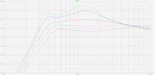
When working simulation, you might start with a 6.5ohm resistance to represent the speaker, and remove R210 & C204. Then balance the bridge by changing the resistance of R209 and until the output of the bridge at pin 7 of IC202 (2/2) is minimized...output will be very small when balanced/nulled correctly.
Then, add inductance and LCR components to represent the mechanical part of the T/S parameters shown in attachment#2 of Post#211. You will now see output from IC202 (2/2) representative of woofer back-EMF(velocity). Finally, you can add back in R210 & C204 to see the small effect it has at improving balance of the bridge at frequencies > 1Khz.
When working simulation, you might start with a 6.5ohm resistance to represent the speaker, and remove R210 & C204. Then balance the bridge by changing the resistance of R209...
Ah, in days of yore (and by theory) you'd want to balance for DC, frequency of lowest impedance point, or glued voice coil when the speaker is connected! Does that make sense?
And simply use a pot between two legs to do the balancing.
Today, you could use THD or 10dB before oscillation or 5 dB before smoke comes from the voice coil.
Not actually do-able in a simulation I suppose, but just wonderin'.
Ben
Last edited:
LTspice simulation done. Is it okay like this? The .zip allows you to reproduce the LTspice simulation.Almost...swap your blue and green wires at CNP103 and you are there.
Attachments
- Home
- Loudspeakers
- Subwoofers
- Commercial motional feedback woofer available sort of