Ben,Patents - and here including IPAL once again - are just tricks to show you own a piece of property trivially different from somebody else's. Werner said it all in 1957.
After re-reading several of your posts, it occurs to me how different the IPAL approach is at making the system's output sound mimic the input signal is from MF systems based on what Werner said in 1957.
The Werner type MF devices you (almost exclusively) describe are using feedback from a sensor directly attached to some portion of the driver. As you have pointed out, in systems such as BR, the cone minima is at Fb, since excursion is greater both above and below, a MF system using a sensor directly attached to some portion of the driver "wouldn't know what to do with it". That same problem would be compounded for horn loaded drivers, which have multiple excursion minima and maxima spread through their pass band.
Since the IPAL sensor detects sound output, not cone motion, the processing it uses is able to apply whatever correction needed to reduce distortion, and because it employs FIR filters which allow for time-based corrections, it can also correct the measured output phase to conform with the input signal's phase.
Note that the corrected sound output is not occurring in "real time" the filters needed to accomplish phase correction do require a short delay, the delay length dependent on the cycle duration of the lowest frequency desired to be "phase correct". Even for live use the delay is virtually inconsequential, for playback use the delay makes no difference unless absolute time lock to video is required.
My mistake was in not properly explaining what I thought would be a quite obvious distinction in the understanding the difference between a motion (only) based feedback system, compared to an output measurement based feedback system. The latter can address every type of output deviation possible, while the former is able to only address a much more limited range of problems on sealed, "infinite" or "open" baffle systems.
Sorry that pointing out the differences has seemed "patronizing" to you, as our input seems to be falling on deaf ears, it is probably time to stop "patronizing" your thread, as I don't believe any new useful data will be seen here.
Cheers,
Art
Last edited:
Interesting you raise the question of horns (meaning true horns, not that weird thing misnamed a tapped horn).That problem would be worse for horn loaded systems, which have multiple excursion minima and maxima spread through their pass band.
For BR boxes, the cone motion around resonance does not reflect total sound output. Therefore, making cone motion right makes the output wrong*.
I don't know if that peculiar situation holds for horns, even though the horn impedance gets reflected back to the cone in complex ways.
But more important, many bass horns have rear sealed boxes, for good reasons. Given the radiation resistance in front of the horn, these boxes can be pretty small. But there they are.
So, horns should be OK for MF. Ran a Klipschorn bass with low feedback-factor MF for a long time..... no problems but I can't say as I noticed much benefit either since true horns are sooooo good. No enclosure needs MF less.
Sadly, often folks at DIYaudio make horn-like structures that really aren't functioning as horns and lack the wonderful virtues of true horns. Too bad.
Ben
*IPAL claims to correct output, not cone motion as your carefully composed (and non-patronizing) post says in the clearest of terms. So that can be OK for BR boxes or any boxes, if it works. But as in the long-ago posts, trying to use a mic to sense output for feedback purposes is like catching sunlight in a bottle. As far as I know, nobody else uses the "naive" approach, so far.
Last edited:
Interesting you raise the question of horns (meaning true horns, not that weird thing misnamed a tapped horn).
For BR boxes, the cone motion around resonance does not reflect total sound output. Therefore, making cone motion right makes the output wrong*.
I don't think that peculiar situation holds for horns.
But more important, many bass horns have rear sealed boxes. Given the radiation resistance in front of the horn, these boxes can be pretty small. But there they are.
So, horns should be OK.
On the other hand, no enclosure needs MF less.
And on the third hand, often folks at DIYaudio make horn-like structures that really aren't functioning as horns and lack the wonderful virtues of true horns. Too bad.
Ben
And here is the problem (or at least a problem). For years now I've been telling you that horns have resonances all through the passband, and yet you still believe they are fundamentally different than bass reflex and that the statement "the cone motion around resonance does not reflect total sound output" does not apply to horns.
You are very wrong about horns, the sealed chamber doesn't make any difference, the resonances are a result of the horn flare and horn resonances look remarkably similar to bass reflex resonances in the excursion graph because resonances are resonances.
Here's a picture to illustrate the point. The top row shows frequency response and excursion of a best case scenario - a single driver in a 4500 liter full size 31 hz ideal reactance annulled front loaded horn with 2:1 compression ratio.
The bottom row shows a much smaller, more practical front loaded horn (370 liters) with the same driver.
If you actually look at this data or at horn measurements (frequency response vs impedance of any horn you like) you will see that "making cone motion right makes the output wrong* is a nonsense statement.
The resonances are an integral part of the nature of horn operation. The horn resonances cause a deep notch in the excursion curve, this is not "wrong", it how it works. It doesn't need to be corrected because it's operating properly. If you did "fix" the excursion by making it linear (no dips) the frequency response would be unusable.
Also the frequency response doesn't need to be "fixed" it's designed to be usable without correction, aside from possibly a bit of minor eq.
You should have noticed this on your own by now, having owned front loaded horns. And if that wasn't enough, I've been telling you this over and over for over 2 years now. Look at the graphs.
An externally hosted image should be here but it was not working when we last tested it.
Sadly, often folks at DIYaudio make horn-like structures that really aren't functioning as horns and lack the wonderful virtues of true horns. Too bad.
This needs to be addressed separately on it's own.
The only horns that truly exhibit "the wonderful virtues of true horns" are true horns. The math is clear on what defines a true horn, it's very large, the mouth size has to have a circumference equal to wavelength at the low knee for example.
Your Klipschhorn was certainly not a "true" horn by any stretch of the definition, even by virtue of being designed for corner use which allows an exponentially smaller mouth. Your antique K horn was a bad design by today's standards with big peaks and dips (resonances) all through the passband and an antique driver that can't hold a candle to today's drivers.
MOST of the horn designs by diy'ers on this forum vastly outperform the old K horn in every way, despite not being "true" horns either.
You need to learn how these things actually work before making patently absurd comments. I can teach you if you like. This stuff is pretty simple.
Interesting you raise the question of horns (meaning true horns, not that weird thing misnamed a tapped horn).
I like this edit you added, it shows you still are not accepting any data provided to you.
Undersized front loaded horns (like your old K horn) are not "true horns" any more than tapped horns are.
Again, see the math for the definition of "true" horns. They are quite well defined and they are huge. Edgar, Leach, Keele and others all have slightly different mathematical definitions of true horns but they are all pretty close to the same thing, all massive and all are nothing at all similar to anything you've ever experienced in your home (or probably anywhere ever).
Ben,1)Interesting you raise the question of horns (meaning true horns, not that weird thing misnamed a tapped horn).
2)For BR boxes, the cone motion around resonance does not reflect total sound output. Therefore, making cone motion right makes the output wrong.
3)I don't think that peculiar situation holds for horns.But more important, many bass horns have rear sealed boxes. Given the radiation resistance in front of the horn, these boxes can be pretty small. But there they are.
4)So, horns should be OK.
5)On the other hand, no enclosure needs MF less.
1) A "true horn" is one that is blown through. A so called "tapped horn" shares some attributes of both FLH and BR designs.
2) The same holds true of what you believe to be a "true horn", only more so, due to multiple resonances.
3) Your not believing facts makes no difference to the fact.
4) No, as anyone can easily see from the excursion in a small rear chamber FLH (and I have, using clear plastic viewing panels) their excursion goes through more than one minima and maxima.
5) Your fifth statement is more or less useless, in light of the fact that your statement #3 ignores facts any horn designer, or anyone familiar in the art is quite familiar with, as this "Art" has been familiar with for over 40 years. In those 40+ years I have been using and designing horns of every description for live use, the most demanding application for reproduction systems. As well as horns, I have extensive use of hybrid dual resonator cabinets, such as the Karlson design, it being the first cabinet I built in 1972, after literally growing up listening to the 8" Karlsons my dad built when I was around 4 years old. Fred, the Karlson Evangelist, now owns those two pieces of my childhood, it is funny how something I thought was "great" 45 years ago was not, after listening to cabinets that have far flatter frequency and phase response for the last 35 years.
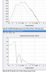
An illustration simulating both the output response as well as the excursion required to achieve said response of a FLH cabinet of approximately 30.5 cubic feet net volume, using dual drivers, with two different driver options, an 18" B&CTBW100, and a 12" Eminence Lab12 are offered for your elucidation below.
I hope you might finally understand you are, and have been, quite far off-based in your understanding of horns. It is quite tiresome for us to continually provide you with educational material which you have usually chosen to ignore or belittle.
I still have some faith you might "see the light", as you finally have started to use DSP and Dual FFT based measurement systems (available for well over three decades now...) recently in this second decade of the 21st century.
Thanks for your consideration, see you in other posts.
Cheers,
Art
Attachments
Last edited:
The common definition for acoustic horn is the simplistic version that follows -
An acoustic horn or waveguide is a tapered sound guide designed to provide an acoustic impedance match between a sound source and free air.
By that definition, the only "true" horns are full size ideal horns, for which the math is clearly defined and can be found all over the internet. Undersized horns don't meet this definition.
First, how do you think this "impedance match", not to mention the huge amounts of in band gain, is realized? It's resonances, all horns have resonances and without resonances you can't have a horn.
Next, let's look at the claimed advantages of horns and how much they apply to full size vs undersized horns, your so called "wonderful virtues of true horns". Hint - undersized horns like your K horn don't have ANY of the wonderful virtues of true horns.
The claimed advantages are -
- pattern control (dispersion)
- acoustic impedance match between a sound source and free air
- high efficiency through the whole passband
I'll go through these one by one and show that the undersized front loaded horns don't have any of these characteristics, only full size front loaded horns do.
And then at the end, I'll show how similar ported boxes are to front loaded horns. Ported boxes have a lot of resonances are operate very similarly to front loaded horns in this respect, although most of the ported box resonances are usually high above the passband and are usually ignored - but that doesn't mean they are not there.
To illustrate what's really going on let's examine a couple of different horns. They are both very large, but one is small compared to the low knee frequency and one is the ideal size (which means it's huge). Both these horns use the same driver but the horns are very different. The small one is still very large at almost 750 liters and with a mouth size of 6550 sq cm but it is still massively undersized compared to it's low knee frequency wavelength. The large one is ideally suited to it's low knee frequency, having a mouth size of over 50000 sq cm and a volume of almost 5000 liters.
Dispersion patterns are a function of size and frequency wave length. If there is a horn or waveguide involved the shape of the flare also has something to do with dispersion.
With tweeters the wavelengths are small because the frequencies are high so it doesn't take a large guide to control their dispersion pattern. With bass horns the wavelengths are large. Does that mean they can't be controlled? Absolutely not.
A small bass horn, the kind you are likely to see being built by a diy'er is much too small to control dispersion at subwoofer frequencies. But a large horn can have a great deal of pattern control.
Let's look at the dispersion patterns of the two example horns. The small one is on the left, the large horn is on the right. The top row is dispersion at 35 hz (near the bottom of the passband), the bottom row is dispersion at 100 hz (top of the passband).
So clearly the small horn is too small to have much effect on directivity even at the top of the passband. The large horn has a small amount of influence over directivity even at the bottom of the passband, and a huge impact at the top of the passband. What goes for tweeters goes for subwoofers too, the difference is frequency vs size, and undersized horns can't control dispersion.
The "impedance transformer" (cone to air) is one of those old sayings that gets passed on all the time but it's not really true at all for small horns. Let's look at the impedance curve of the two example horns. Small on left, large on right.
The small horn has an impedance curve that looks a lot like a transmission line, which we know is not considered an impedance transformer. The large horn's impedance curve is much different. The spikes are damped, the dips are not as deep and the average level in the passband is higher.
In the small horn there are narrow bands of very high efficiency corresponding to the huge impedance spikes and in between the spikes the efficiency is very low. The large horn has a higher level of efficiency across the entire passband due to it's sheer size and a much more calm impedance curve. This is what they mean by impedance matching and it doesn't apply to small horns. The impedance curve is where you see it but that's not really what they are talking about either. What they mean is that the impedance curve, the frequency response and everything else is smooth, not spiky so the cone is able to "see" a more constant radiation resistance in the air load at all frequencies in the passband.
Here's actual efficiency. Small horn on left, large on right, 120 liter ported box tuned to about 32 hz on bottom. The small horn does have a lot more efficiency than the much smaller ported box at most frequencies, that's to be expected based on size and having so many impedance peaks inside the passband. The large horn efficiency is much higher than both.
Clearly efficiency spikes at the same frequencies the impedance peaks are at. So if you line up a bunch of impedance peaks inside the passband you can have boosted efficiency for as much as a 3 octave passband. And the larger the enclosure, the more acoustic gain, the more efficiency.
Some people might not be aware of what the ported box is actually doing. The front wave is out of phase with the back across a lot of the passband so they are actually fighting each other. At some frequencies the direct radiator output wins and at others the box resonances win. It's a complex summation. This is the direct radiator output (left), the port output (right) and the summed response (bottom).
For people that only use WinISD or similar helmholtz type simulators it may not be clear that ported boxes have a series of resonances like a horn. But when you look at port output alone in a picture like that directly above it becomes clear that ported boxes have ALL KINDS of resonances. The people who are aware that there are ported box resonances usually just ignore them, thinking they will be too far above the passband to matter.
But when you look at the port output image it becomes clear that ported boxes and horns are not really all that different. The horn actively uses it's shape to line all those resonances up into a pretty row and give them the individual acoustic gain that they need to provide a propped up flat(ish) response over as much as 3 octaves. The ported box has the same type of resonances but they are at erratic frequencies where they can't help but can only cause trouble. Therefore the resonances need to be pushed up way out of the passband or stuffing must be applied to calm them down. MLTL and the various different types of TL are ported box variants that attempt to make use of ported box resonances instead of ignoring them or stuffing the life out of them. Some types of TL are remarkably similar to undersized horns.
The resonant enclosure types are not that different, they all lie on a continuum based on shape and layout. They all have a series of resonances. How they deal with these resonances might be different but they all have them.
An acoustic horn or waveguide is a tapered sound guide designed to provide an acoustic impedance match between a sound source and free air.
By that definition, the only "true" horns are full size ideal horns, for which the math is clearly defined and can be found all over the internet. Undersized horns don't meet this definition.
First, how do you think this "impedance match", not to mention the huge amounts of in band gain, is realized? It's resonances, all horns have resonances and without resonances you can't have a horn.
Next, let's look at the claimed advantages of horns and how much they apply to full size vs undersized horns, your so called "wonderful virtues of true horns". Hint - undersized horns like your K horn don't have ANY of the wonderful virtues of true horns.
The claimed advantages are -
- pattern control (dispersion)
- acoustic impedance match between a sound source and free air
- high efficiency through the whole passband
I'll go through these one by one and show that the undersized front loaded horns don't have any of these characteristics, only full size front loaded horns do.
And then at the end, I'll show how similar ported boxes are to front loaded horns. Ported boxes have a lot of resonances are operate very similarly to front loaded horns in this respect, although most of the ported box resonances are usually high above the passband and are usually ignored - but that doesn't mean they are not there.
To illustrate what's really going on let's examine a couple of different horns. They are both very large, but one is small compared to the low knee frequency and one is the ideal size (which means it's huge). Both these horns use the same driver but the horns are very different. The small one is still very large at almost 750 liters and with a mouth size of 6550 sq cm but it is still massively undersized compared to it's low knee frequency wavelength. The large one is ideally suited to it's low knee frequency, having a mouth size of over 50000 sq cm and a volume of almost 5000 liters.
An externally hosted image should be here but it was not working when we last tested it.
Dispersion patterns are a function of size and frequency wave length. If there is a horn or waveguide involved the shape of the flare also has something to do with dispersion.
With tweeters the wavelengths are small because the frequencies are high so it doesn't take a large guide to control their dispersion pattern. With bass horns the wavelengths are large. Does that mean they can't be controlled? Absolutely not.
A small bass horn, the kind you are likely to see being built by a diy'er is much too small to control dispersion at subwoofer frequencies. But a large horn can have a great deal of pattern control.
Let's look at the dispersion patterns of the two example horns. The small one is on the left, the large horn is on the right. The top row is dispersion at 35 hz (near the bottom of the passband), the bottom row is dispersion at 100 hz (top of the passband).
An externally hosted image should be here but it was not working when we last tested it.
So clearly the small horn is too small to have much effect on directivity even at the top of the passband. The large horn has a small amount of influence over directivity even at the bottom of the passband, and a huge impact at the top of the passband. What goes for tweeters goes for subwoofers too, the difference is frequency vs size, and undersized horns can't control dispersion.
The "impedance transformer" (cone to air) is one of those old sayings that gets passed on all the time but it's not really true at all for small horns. Let's look at the impedance curve of the two example horns. Small on left, large on right.
An externally hosted image should be here but it was not working when we last tested it.
The small horn has an impedance curve that looks a lot like a transmission line, which we know is not considered an impedance transformer. The large horn's impedance curve is much different. The spikes are damped, the dips are not as deep and the average level in the passband is higher.
In the small horn there are narrow bands of very high efficiency corresponding to the huge impedance spikes and in between the spikes the efficiency is very low. The large horn has a higher level of efficiency across the entire passband due to it's sheer size and a much more calm impedance curve. This is what they mean by impedance matching and it doesn't apply to small horns. The impedance curve is where you see it but that's not really what they are talking about either. What they mean is that the impedance curve, the frequency response and everything else is smooth, not spiky so the cone is able to "see" a more constant radiation resistance in the air load at all frequencies in the passband.
Here's actual efficiency. Small horn on left, large on right, 120 liter ported box tuned to about 32 hz on bottom. The small horn does have a lot more efficiency than the much smaller ported box at most frequencies, that's to be expected based on size and having so many impedance peaks inside the passband. The large horn efficiency is much higher than both.
Clearly efficiency spikes at the same frequencies the impedance peaks are at. So if you line up a bunch of impedance peaks inside the passband you can have boosted efficiency for as much as a 3 octave passband. And the larger the enclosure, the more acoustic gain, the more efficiency.
An externally hosted image should be here but it was not working when we last tested it.
Some people might not be aware of what the ported box is actually doing. The front wave is out of phase with the back across a lot of the passband so they are actually fighting each other. At some frequencies the direct radiator output wins and at others the box resonances win. It's a complex summation. This is the direct radiator output (left), the port output (right) and the summed response (bottom).
An externally hosted image should be here but it was not working when we last tested it.
For people that only use WinISD or similar helmholtz type simulators it may not be clear that ported boxes have a series of resonances like a horn. But when you look at port output alone in a picture like that directly above it becomes clear that ported boxes have ALL KINDS of resonances. The people who are aware that there are ported box resonances usually just ignore them, thinking they will be too far above the passband to matter.
But when you look at the port output image it becomes clear that ported boxes and horns are not really all that different. The horn actively uses it's shape to line all those resonances up into a pretty row and give them the individual acoustic gain that they need to provide a propped up flat(ish) response over as much as 3 octaves. The ported box has the same type of resonances but they are at erratic frequencies where they can't help but can only cause trouble. Therefore the resonances need to be pushed up way out of the passband or stuffing must be applied to calm them down. MLTL and the various different types of TL are ported box variants that attempt to make use of ported box resonances instead of ignoring them or stuffing the life out of them. Some types of TL are remarkably similar to undersized horns.
The resonant enclosure types are not that different, they all lie on a continuum based on shape and layout. They all have a series of resonances. How they deal with these resonances might be different but they all have them.
Ran a Klipschorn bass with low feedback-factor MF for a long time..... no problems but I can't say as I noticed much benefit either since true horns are sooooo good. No enclosure needs MF less.
So many edits to your original post.
As I mentioned with loads of detail in the last few posts, you can't "correct" cone motion in horns with MF in the traditional sense, as the cone motion dips at resonances are not an error and it's not supposed to be a smooth excursion curve. So whatever you did with MF and that K horn, it wasn't what you thought and probably made the situation worse. I told you that a few times earlier in this thread.
And also, as shown, the K horn is not a true horn and not even a very good horn.
bolserst -
I've been pondering your high-class engineering way of looking at MF.... last night i was reading about beam and truss analysis for big buildings.
Can a person set up an MF system and measure the active T/S parameters? Sort of the way I earlier described measuring negative output impedance in an MF amp.
I don't know if that makes sense since MF is only meaningful in when moving while the familiar electrical-equivalents (T/S) are mostly static and for unhoused drivers.
If we had "active T/S parameters" for drivers under MF (or under MF given a specific housing), then we could model performance in speakers to see if it all coheres vis a vis acoustic measurements.
I know this is all confused, but welcome your thoughts.
Ben
Ben,*IPAL claims to correct output, not cone motion as your carefully composed (and non-patronizing) post #341 says in the clearest of terms. So that can be OK for BR boxes or any boxes, if it works. But as in the long-ago posts, trying to use a mic to sense output for feedback purposes is like catching sunlight in a bottle. As far as I know, nobody else uses the "naive" approach, so far.
I forgot to address your * point in my previous reply #346, which addressed your other 5 points from post #342.
IPAL does indeed correct the systems output to match the input, though the way it accomplishes that is nothing like "catching sunlight in a bottle".
Electricity travels at (for all intents and purposes) the speed of light, 983,941,524 feet per second, while sound waves "slog along" at only 1130 feet per second. With the speed difference between electricity and sound being so huge, and modern microprocessor speed easily capable of making slight delay adjustments at thousands of computations in a single LF sound wave, you are quite naive if you think the IPAL approach is.
Perhaps the reason that you don't know of anyone else using the IPAL approach it the patent is still enforceable, unlike decades old, obsolete technologies that are far superseded by their advanced technological integrated approach to speaker problems that the vast majority of potential audience care nothing about.
In other words, IPAL has succeeded in doing exactly what they set out to do, make a speaker output match the input signal over the entire usable range of the chosen driver, yet even if they capture 100% of the market share of the purchasers who care enough to spend the additional cost to implement their product, the returns from it's sales will be will be but a very tiny drop in the bucket compared to Powersoft's global amplifier sales.
Art
Meyer Sound, another nobody using microphone MFB
I think I saw a price of 30,000 British pounds* and must be tuned to your room by their techie. This write-up, after my apology, is quite informative.
I humbly beg everybody's pardon if I ever led them to think that I never in the future history of technology thought anybody would ever get the computational part of MF using a mic and individually tuned rooms completed. I was wrong. It is possible but it still costs 30,000 pounds.
Ben
*don't faint, that's the price for a pair
Naturally, there is more to it than this in practice — integrating a feedback servo system with a reflex-loaded loudspeaker is far from straightforward, mainly due to non-linearities caused by the resonance of the tuned cabinet as well as those in the driver itself. This is a very complex problem to solve, and one which has defeated all previous attempts. Indeed, many audio veterans will recall some of the disastrous attempts in the past — the one I remember best was Philips' 'motional feedback' which, although quite effective with a slow swept tone on the test-bench, sounded like it was underwater when replaying music!
Meyer had experimented with a servo design during the development of the HD1, but without success. However, very sophisticated mathematical techniques called Mu-Control (see box on page 138) have been developed for the design of complex servo-feedback systems and they are now capable of dealing with the complexities of a loudspeaker system. Meyer Sound call their implementation of this servo system 'Pressure Sensing Active Control' (PSAC) and it was developed in conjunction with the University of California in Berkeley.
Applying and refining the PSAC technology took around a year. Before the servo system could even be designed, a 'model' of how the complete loudspeaker/cabinet worked had to be developed, as the servo can only generate its correcting signal if it is 'aware' of the way the loudspeaker system works. This is, clearly, the hard part of the problem, but once all the various controlling inputs (air pressure, amplifier current and voltage) and desired outcomes (minimal distortion, flat frequency and phase response) have been accurately specified and modelled, a series of mathematical equations describing the servo are derived. From these equations, the electronic circuitry (or even DSP algorithms) can be constructed to implement the servo in hardware.
The main controlling input to the PSAC system is feedback of the air pressure wave emanating from the driver. This pressure wave is measured with a microphone mounted on a bar directly in front of the bass driver. This has to withstand SPLs in excess of 150dB on peaks and requires a flat response down to 1Hz to maintain stability in the servo controller. Other feedback information is derived from current and voltage sensing at the output of the bass amplifier which ensures the drive unit remains within safe working limits.
The use of a microphone as the main controller input means that the servo system is, to some degree, inherently sensitive to external sound, including room reflections. When I was shown the Meyer X10s, I was amazed to notice that the bass cone moves visibly in response to the low-frequency pressure change caused by opening a door to the listening room. In practice, this means that it is imperative for the system to be carefully aligned and tuned to its environment during the installation.
One of the problems which defeated earlier attempts at feedback-control systems was the apparent delay — it takes a finite time for the speaker diaphragm to move in response to an input signal. Intuitively, using a microphone a few inches in front of the cone to sense the pressure wave it creates would seem to make this situation even worse. However, at such low frequencies we are not really talking about delay but, rather, a phase shift. The Mu-control design technique allows the servo to be designed to accommodate this.
Hi bentoronto,
I mentioned earlier (post#194) besides Meyer, A.C.T. (small German 'hifi/HT' OEM of Klaus Gruber) also used 'pressure' for their feedback systems.
Cheers,
Djim
I mentioned earlier (post#194) besides Meyer, A.C.T. (small German 'hifi/HT' OEM of Klaus Gruber) also used 'pressure' for their feedback systems.
Cheers,
Djim
Hi Djim,
Haven't been able to find any data beyond the fact that A.C.T./Klaus Gruber used a microphone in front of the cone as mfb signal pickup. Do you have any links?
Regards,
Haven't been able to find any data beyond the fact that A.C.T./Klaus Gruber used a microphone in front of the cone as mfb signal pickup. Do you have any links?
Regards,
Ben,1)The use of a microphone as the main controller input means that the servo system is, to some degree, inherently sensitive to external sound, including room reflections. When I was shown the Meyer X10s, I was amazed to notice that the bass cone moves visibly in response to the low-frequency pressure change caused by opening a door to the listening room. In practice, this means that it is imperative for the system to be carefully aligned and tuned to its environment during the installation.
2)One of the problems which defeated earlier attempts at feedback-control systems was the apparent delay — it takes a finite time for the speaker diaphragm to move in response to an input signal. Intuitively, using a microphone a few inches in front of the cone to sense the pressure wave it creates would seem to make this situation even worse. However, at such low frequencies we are not really talking about delay but, rather, a phase shift.
Meyer Sound is, and always has been, a USA company based out of San Francisco, their product line has always been sold in US dollars, though the exchange rate to other currency has obviously fluctuated.
Their current microphone sensor , digitally controlled feedback studio monitors don't cost anywhere near the equivalent of 30K British Pounds.
1)Yes, "to some degree" the microphone is sensitive to sound reflections, at the inverse distance law- it is fairly easy to determine that at a drop of 6 dB per doubling of distance the reflection from several feet away will be so far down in the noise floor that the guy "tuning" the system is simply collecting a "good will" fee.
2) Yes, that was a problem back in the days of wooden ships, iron men and analog systems 🙄.
Fortunately, in the modern digital era, relative time/phase correction has become a trivial pursuit.
Cheers,
Art
I agree. Well, unless you use a coil that operates in its own magnetic circuit, physically separate from the main driving VC. Of course then you would have to deal with mechanical resonance resulting from mounting a mass distant from the driving force of the main VC. This same resonance issue defines the upper frequency limit on accelerometer based systems as well.So, any kind of velocity sensing seems to have a use limited to sub-woofers.
+1Ben, the back-EMF is there absolutely, as you state, but it is very small compared to the current sensed by the resistor.
The purpose of the bridge is to remove the large contribution of the amplifier from the signal so you are left with the small contribution from the back-EMF that is useful for MFB control of the VC motion. There is no magnification, just simple subtraction if bridge is in balance.While the bridge approach magnifies the error component of the feedback signal, I think the main purpose of using it…is to balance those other pesky impedance gremlins by modelling them in the contra-leg.
At frequencies above resonance, the inductive nature of the impedance does throw the bridge out of balance as you alluded to. In practice complete compensation is nearly impossible, so VC feedback is really only useful at frequencies below this point. Also, even small levels of VC heating throws the bridge out of balance as I showed data for back in Post#209.
I don’t think you can measure them directly. You would need to measure the complex output impedance of the MF amplifier system and the native T/S parameters of the woofer separately. Then, you could calculate the effective T/S parameters based on those two measurements.bolserst -
Can a person set up an MF system and measure the active T/S parameters? Sort of the way I earlier described measuring negative output impedance in an MF amp.
On the contrary, quite clear and straight forward question…something I had thought about doing some years ago. But in the end, just using the formulas provided by Stahl to calculate them based on circuit values was much easier and matched modeling quite well.If we had "active T/S parameters" for drivers under MF (or under MF given a specific housing), then we could model performance in speakers to see if it all coheres vis a vis acoustic measurements.
I know this is all confused, but welcome your thoughts.
Hi Y'all,
Looking into the problem of applying MFB to bass-reflex enclosures I found an interesting project report (Imperial College London, Final Year Project Report 2007):
http://www.bycgwtsf.com/downloads/ic_final_report.pdf
Here an attempt was made at applying motion feedback to a passive radiator subwoofer by attaching a transducer to the active driver, and another transducer to a passive radiator, and processing the resultant signals in a Texas Instruments DSP. While not fully successful this looks like an interesting approach.
Maybe something similar could be done by measuring air flow velocity in a bass-reflex port(duct)? Once the move to a custom DSP has been made all kinds of things look almost possible. 🙂
Regards,
P.S.: Obviously, using regular drivers as passive radiators provides one w/ a sensing coil.
Last edited:
Nice creative thinking.Maybe something similar could be done by measuring air flow velocity in a bass-reflex port(duct)? Once the move to a custom DSP has been made all kinds of things look almost possible. 🙂.
But with MF, you are driving a voice coil and trying to instantaneously correct little crooked bits of every single cycle. So the feedback signal must be unconditionally precise, predictable, and unvarying down to degrees of phase.
Which is why sticking mic in the air in front of the speaker, even if that sounds like the natural and naive way to do it, is challenging. Even more challenging would be sensing air flow in a port or vibrations in a passive radiator.
Ben
- Home
- Loudspeakers
- Subwoofers
- Commercial motional feedback woofer available sort of