Square Wave Visualizer for Mag & Phase Response
I went ahead and added a curve for group delay since it had been mentioned a few times.
The [Directions] TAB should hopefully answer any questions on its use.
The *.zip file contains two file.
The *.xls file is for running with older versions of Excel.
The *.xlsm file is for running with Excel 2007 or newer.
A short macro code is used, so when you open the spreadsheet be sure to enable Macro content when prompted.
You will also need to have the Analysis Toolpak Add-In installed and active for the complex number calculations in the spreadsheet to work. If you are getting flat-line responses when changing anything, a quick web search for will find you plenty of details on how to install and select/activate it.
Apologies for not getting this posted earlier...just too many irons in the fire.i'd like the spreadsheet Please, it sounds very handy 😉 Your 3 graphs illustrate things nicely 🙂
I went ahead and added a curve for group delay since it had been mentioned a few times.
The [Directions] TAB should hopefully answer any questions on its use.
The *.zip file contains two file.
The *.xls file is for running with older versions of Excel.
The *.xlsm file is for running with Excel 2007 or newer.
A short macro code is used, so when you open the spreadsheet be sure to enable Macro content when prompted.
You will also need to have the Analysis Toolpak Add-In installed and active for the complex number calculations in the spreadsheet to work. If you are getting flat-line responses when changing anything, a quick web search for will find you plenty of details on how to install and select/activate it.
Attachments
Hi bolserst,
Thanks for the spreadsheet, it makes visualization so much easier. I used the .xlsm file in Excel 2007 (Windows 10), and it seems to work fine.
Regards,
Thanks for the spreadsheet, it makes visualization so much easier. I used the .xlsm file in Excel 2007 (Windows 10), and it seems to work fine.
Regards,
2) Yes, that was a problem back in the days of wooden ships, iron men and analog systems .
Fortunately, in the modern digital era, relative time/phase correction has become a trivial pursuit.
You actually can't do "in digital" what physics and maths don't let you do "in analog". You can of course correct a whole speaker's phase very accurately with DSP and FIR filtering. But the method of choice is adding the inverse greoup delay to the overall transfer function such that it isn't reduced where it is highes (which would require a time-machine) but it is elevated where it is lowest. Such a correction would not be helpful within a feedback loop.
Fortunately it is possible to use old-fashioned analog EQ circuits (and their digital equivalent: IIR filters) that allow the correction of amplitude AND phase at the same time.
If someone wants to know the details of the PSAC simply read the patent which is quite explicit:
Patent US6584204 - Loudspeaker system with feedback control for improved bandwidth and ... - Google Patents
The method used in the German ACT subwoofer that was mentioned before was invented by Backes & Mueller originally, although this patent here doesn't mention the preferred mounting method of the mic capsule:
Patent EP0171065A2 - Arrangement for the acoustic feedback of loudspeakers - Google Patente
For really high quality applications it may be quite difficult to find a suitable microphone. I always wondered what Meyer might use. Because it is in the feedback path its nonlinear distortion is directly influencing the system's response.
The worst transducers in this respect are those piezo-resistive pressure sensors which could withstand horrendous SPLs on the one hand but which show hysteretic behaviour OTOH.
Regards
Charles
Last edited:
Thanks. That helps clear the air.
The "naive approach" - sticking a mic in front of the driver (in the linked patent, one finger-width from the dust cap) - means you are dependant on a mic with an inconceivable dynamic range to control your well-made driver. Or a $12 accelerometer.
MF design, like all good design, proceeds from knowing your requirements. With a different goals for moving to MF control, good to think that through first.
Ben
Ben,The "naive approach" - sticking a mic in front of the driver (in the linked patent, one finger-width from the dust cap) - means you are dependant on a mic with an inconceivable dynamic range to control your well-made driver.
A typical back electret microphone as used in telephones and recording devices, the element costing around $5, has dynamic range in excess of that of a well-made driver.
No idea why you would think that dynamic range is "inconceivable", but you do seem to continue to show your naivety so frequently I have stopped wondering why.
If you really want to throw money around, you could use a condenser microphone like the B&K 4004 using it's 130 volt phantom power supply. The B&K 4004 has 148 dB dynamic range with <1% THD,153 dB with <1% differential frequency distortion, but that choice would be overkill for a motional feedback microphone loop.
I do happen to have a pair of 4004, but only because they were willed to my brother, and he gifted them to me. They have a frequency response +/- 2 dB from 10 Hz to 40 kHz, and individual factory test charts for each microphone.
Because of their value and rarity, I generally use a $50 test microphone instead, though it is a few dB down at 20 Hz from the 4004s.
Art
Charles,You actually can't do "in digital" what physics and maths don't let you do "in analog". You can of course correct a whole speaker's phase very accurately with DSP and FIR filtering. But the method of choice is adding the inverse greoup delay to the overall transfer function such that it isn't reduced where it is highes (which would require a time-machine) but it is elevated where it is lowest.
There seem to be several posters in this thread that just don't get the concept of FIR filters, obviously my efforts to explain them are ineffective in explaining both how they work, and how they defy no known laws of physics.
Analog tape loop and bucket brigade analog delays have been around for ages, they have been used for various functions, but are not really up to the tasks we would ask them to do in a MF circuit without expending far too much money for too little performance.
Digital delays allow a "time-(delay)machine" function to be employed in FIR filters, the entire filter has the same group delay as the lowest frequency to be corrected. A sensor's output can be delayed by the corresponding amount to provide "real time" (although slightly delayed from the original signal) feedback of the drivers phase and harmonic distortion.
It's not "rocket science" it's "computer science", 1s and 0s, recorded, stored and retrieved in a precise fashion that makes things that were not possible in an analog circuit quite possible, as can be seen in the phase response of speakers employing FIR filters- flat phase, going as low as designed, the only limitation being the latency from when you hit "play" to when the sound comes out of the loudspeaker. The latency to achieve flat phase to 20 Hz is far less than the time from hitting "play" on a CD player to when it starts playing.
Art
How silly of me to use such extreme language as "inconceivable". Why any budd on this forum can go right today to the B&H Photo website and buy a 4004 for us$2,429.95 (ummm, might be some tax, I don't know). If you have stereo subs, that comes to an ALMOST inconceivable price of us$4,960, roughly, plus tax.I do happen to have a pair of 4004, but only because they were willed to my brother, and he gifted them to me. They have a frequency response +/- 2 dB from 10 Hz to 40 kHz, and individual factory test charts for each microphone.
Because of their value and rarity, I generally use a $50 test microphone instead, though it is a few dB down at 20 Hz from the 4004s.
And if you don't feel your music enjoyment is worth every penny and more, Art knows of $5 cellphone electrets for you.
Does anybody have the math skills to explain the ballpark the mic has to play in when one finger-width from the dust cap?
Ben
Last edited:
Hi Y'all,
No math skills here. 🙂 But, in general: dynamic microphones are very low noise, and very hard to overload. Here are two links to Shure customer help with some data as to the noise and overload characteristics of dynamic microphones:
Can a dynamic microphone handle really loud sounds? (Maximum SPL) | Shure Technical FAQ)
What are the noise specs for a dynamic mic, like the SM58? | Shure Technical FAQ
In the late 1970s I used to build some small 6" cubes w/ 4.5" fullrange speakers for monitoring purposes. I played around w/ these as microphone substitutes, e.g.: drums, and was pleasantly surprised about the quality of the sound, and the overload capability.
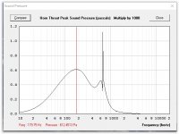
Just for fun I simulated a very short horn for a B&C 18SW115 w/ a drive voltage of 120Vac, the throat pressure peaked out @ 612Pa/180Hz. A normal driver installation @ more reasonable level should be quite a bit lower. 🙂
Regards,
No math skills here. 🙂 But, in general: dynamic microphones are very low noise, and very hard to overload. Here are two links to Shure customer help with some data as to the noise and overload characteristics of dynamic microphones:
Can a dynamic microphone handle really loud sounds? (Maximum SPL) | Shure Technical FAQ)
What are the noise specs for a dynamic mic, like the SM58? | Shure Technical FAQ
In the late 1970s I used to build some small 6" cubes w/ 4.5" fullrange speakers for monitoring purposes. I played around w/ these as microphone substitutes, e.g.: drums, and was pleasantly surprised about the quality of the sound, and the overload capability.
Just for fun I simulated a very short horn for a B&C 18SW115 w/ a drive voltage of 120Vac, the throat pressure peaked out @ 612Pa/180Hz. A normal driver installation @ more reasonable level should be quite a bit lower. 🙂
Regards,
Attachments
And if you don't feel your music enjoyment is worth every penny and more, Art knows of $5 cellphone electrets for you.
This is disingenuous at an extreme level. Just because a $5 part will work doesn't necessarily mean it's a compromise and you need to spend $5000. If that were true, all the 1970's amps you buy at goodwill would be necessarily garbage because they don't have exclusively mil spec resistors and "audiophile" boutique caps and the most expensive op amps on the market, etc.
Does anybody have the math skills to explain the ballpark the mic has to play in when one finger-width from the dust cap?
Ben
Since there are already existing products using this tech it isn't really necessary to explain anything. The products exist, they work, they work well, and I guarantee they don't use $5000 mics.
Hi phase_accurate,
The use of a mic for a feedback signal was at least 'invented' in the 50ties, by Bekey for instance.
Cheers,
Djim
The use of a mic for a feedback signal was at least 'invented' in the 50ties, by Bekey for instance.
Cheers,
Djim
Ben,And if you don't feel your music enjoyment is worth every penny and more, Art knows of $5 cellphone electrets for you.
Yes, and those $5 back electret microphone elements are the same as used in many test microphones that have been used by thousands of DIY folks such as yourself, and professional engineers for testing tens of thousands of loudspeakers.
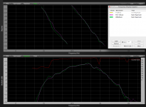
You can see for yourself in the measurements below that the $2.50 Panasonic WM62 (1998 new element only price, less phantom power supply) reads almost identical to the $50 (used, 2010) RTA-420 test mic. Both mics were placed in as close to the same position during the tests as I could manage short of using a micrometer.
The RTA-420 reads almost the same as the B&K 4004, though there is a HF deviation between the two B&K 4004 that puts the RTA-420 as a closer match to one of them than the pair. As mentioned, the RTA is about 2 dB down at 20 Hz compared to the B&K 4004.
You don't need to spend big $$$ to have reasonably accurate gear, but if you want to go "all the way", the tickets get expensive, and don't insure results- the test mic that came with a $1600 Terrasonde Audio Toolbox that I was sure was "the real deal" was about 10 dB down at 20 Hz, the worst response of any back-electret mic I measured, other than flat out defective ones. I did not discover the problem until I started testing my test mics.
I'd be willing to wager your average cost per year keeping your stereo system alive with a few changes every decade or so is considerably less than what most people spend on coffee.
Nothing wrong with being cheap, but there is no excuse for ignorance when the information is at your fingertips- try spending your time looking up some concepts, rather than the price of my esoteric mics, and you might actually come closer to achieving your audio goals.
That said, it is patently obvious you are not on the forum to learn or achieve any audio goal, you are here to troll.
Everybody has a purpose 😉
Cheers,
Art
Attachments
Apologies for not getting this posted earlier...just too many irons in the fire.
Steve - your message box is full and so I can't respond.
There is a lot of confusion here. Just obey the facts. Sony applies voltage feedback (just as normal) and also current feedback (the 0.22 ohm resistor voltage drop processed by an op-amp). Same as the Yamaha YST-series subwoofers. Such current feedback is a positive feedback. The more output current, the more output voltage. As consequence, the power amplifier emulates a negative output impedance, say - 2.5 ohm. Such negative impedance comes in series with the voice coil copper resistance, say + 3.5 ohm. The system behaves like there is a woofer having a 1.0 ohm copper resistance. The woofer electric damping has thus significantly improved in the low frequencies. This is a significant Thiele-Small parameter change (should I write optimization).Thanks to all for largely sensible discussion. MF in a ported tuned box is totally screwball, but yet still within the territory of HiFi screwballland. Anyone with an understanding of the perverse relation between cone motion and sound output in a BR will understand why. Of course, maybe that wouldn't stop Sony. Even if MF in a BR is actually counter-productive in the bass region, it has benefits everywhere else in the compass. And it is possible, the tuning is nothing like the usual TS-BR theory and it does work beneficially in some unusual way with MF.
I wrote "in the low frequencies" because the voice coil inductance is made of resistance (copper material) and inductance (coil shape having an iron core). The Yamaha/Sony system only decreases the copper resistance. It doesn't reduce the coil inductance. At 1 kHz, in case the coil inductance is 0.5 mH, the module of the inductive impedance rises to 3.14 ohm, indicating that at 1 kHz, the electric damping doesn't get improved anymore. This is the reason why such simple positive curent feedback, gets confined to subwoofers having a bandwidth of 100 Hz or so.
One may try adding a small coil in series say 33 µH with the 0.22 ohm resistor acting as current sensor. This way the positive feedback voltage will take into account the inductive nature of the voice coil, possibly extending the electric damping effect to 300 Hz or so. Try designing a bass-reflex enclosure having a 12-inch woofer only exhibiting a 1.0 copper resistance. Good luck !
Do you get a realistic box size, and a realistic port length and section ?
If not, revert to a closed-box approach.
You'll reinvent the "Servo-Sound SL15" or "Servo-Sound SL20" dating back from 1969.
You'll reinvent the "3A Andante" dating back from 1974.
Anyway, can we say that the woofer coil, truly behaves like a 3.5 ohm resistor having a 0.5 mH coil in series?
Problem is the resistor value. Copper has a thermal coefficient. The copper resistance value depends on the temperature. The residual (virtual) 1.0 ohm resistance will vary in function of the temperature. For remaining safe, the positive current feedback should remain moderate, never suppressing more than 80% of the coil resistance. Indeed, as soon as the coil resistance suppression goes over 100%, you end up with a residual (virtual) negative resistance, forming an oscillator.
Problem is the inductance value. We face an iron-core coil. There are eddy currents in the iron core, lowering the effective inductance. There may be magnetic hysteresis, causing distorsion. And the coil slides along the iron-core, complicating the behavior (becoming frequency dependent). The eddy currents may be short-circuited using a copper ring or sleeve. Woofers equipped with a copper ring or sleeve exhibit less inductance. Prof. W. M. Leach, Jr. was the specialist in such field. He published a couple of papers dealing with the Loudspeaker Voice-Coil Inductance, and the ways for properly model it. See them here : Dr. Leach's Refereed Papers.
Worth reading are people like Ahmet Feyz Pirimoglu here : http://www.diy-audio.narod.ru/litr/FaradayRingsVoiceCoilImpedance.pdf
IMO, positive current feedback gets problematic above 300 Hz or so.
Cloning a "3A Andante" is easy nowadays.
See it here : http://www.acoustique-3a-by-daniel-dehay.com/depannage-d-une-asservie-3a
You shall base on the Visaton Vision BS kit : Strassacker, Komponenten: Lautsprecher, Frequenzweichen, Bauelemente
There is a lot of confusion here. Just obey the facts. Sony applies voltage feedback (just as normal) and also current feedback (the 0.22 ohm resistor voltage drop processed by an op-amp). Same as the Yamaha YST-series subwoofers. Such current feedback is a positive feedback.
I don't think so. Current feedback normally is negative feedback, just like voltage feedback. What they might have done is split the feedback in a current part and a voltage part, each derived from a mirrored high/low filter. I did the experiment with an LM3886 in an attempt to lower driver distortion; voltage feedback in the resonance region of the driver, transitioning to current feedback for higher frequencies. It works, but dunno if this is what Sony did. Positive feedback seems out of the question, though.
Think twice. Get the schematic and simulate it using LTspice. Try with a closed box first.I don't think so. Current feedback normally is negative feedback, just like voltage feedback.
In the Sony / Yamaha subwoofers applications (vented box), the positive current feedback is there for significantly reducing the virtual coil resistance (from 3.6 ohm to say 1.8 ohm), kind of Thiele-Small parameter optimization in function of the wanted box size and vent size. Yamaha adds a trick. When the woofer tends to get overloaded, a FET progressively makes a short circuit on the current feedback signal. Consequently, the virtual woofer coil resistance progressively increases from say 1.8 ohm, to the 3.6 ohm physical value. Consequently, the woofer current gets progressively reduced by 6 dB. This provides a 6 dB headroom extension, causing less audible artefacts than adding a FET limiter at the input.
In a closed box application, the positive current feedback is there for radically reducing the apparent coil resistance (from 3.6 ohm to say 0.9 ohm) for attaining a very low Q factor. The lower the Q factor, the more the frequency response tends to a 1st-order highpass between 35 Hz and 100 Hz. Add a 1st-order equalizer at the input (bass boost with two resistors and one capacitor), and you get a frequency response that's essentially flat from 35 Hz to 100 Hz, and this remains true when the box is small.
By the way this is not MFB (Motional FeedBack). Call it degenerated EMFB maybe (Estimated Motion FeedBack).
MFB means "feedback based on real motion". MFB should thus rely on a mechanical sensor, like an accelerometer (Philips MFB).
EMFB should base on a circuit taking the voice coil current as input, and estimating the instantaneous voltage drop caused by the voice coil impedance (which is more elaborate than a resistor and an inductor in series).
You then subtract such voltage drop from the actual voice coil voltage.
The result of the subtraction is the motional voltage, which is directly proportional to the coil speed, to the coil motion should we say.
And, you shall use such motional voltage, as sole and only global negative feedback. Or possibly, such global feedback governing a power amplifier having a voltage amplification of 1,000 (one thousand) or so.
Good luck ! Most of the time you end up building an oscillator.
The best you can do is to elaborate the voltage drop, and only discount 80% of it, from the actual coil voltage. This, in the context of a power amplifier having a voltage amplification of 150 or so (about 4 times more than what you really need). This way you implement a 80% EMFB system, that should remain stable.
Attachments
Last edited:
Truly helpful discussion to re-think MF in terms of "system T/S" rather than "driver T/S", as bolserst started earlier. Like to hear more.The lower the Q factor, the more the frequency response tends to a 1st-order highpass between 35 Hz and 100 Hz. Add a 1st-order equalizer at the input (bass boost with two resistors and one capacitor), and you get a frequency response that's essentially flat from 35 Hz to 100 Hz, and this remains true when the box is small.
By the way this is not MFB (Motional FeedBack). Call it degenerated MFB maybe.
About "system Q", always seems peculiar to aim for anything but the lowest Q. Certainly there is no "critical" Q that speaker builders should aim for as a goal; and despite the magic of calling it "critical", in reproduction, deader is better.* MF can bring that about as steph_tsf indicates... exactly the way voltage feedback in an amp brings about the cherished low output impedance that wouldn't be feasible any other way.
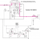
What about the first-order correction steph_tsf talks about, with that FET and the mysterious over-engineered ANIC circuit board in the Yamaha attachment? Voice coil feedback relates to cone velocity and in the low frequencies that translates to a first-order roll-off. That is easily corrected with first-order EQ.
Is that another way to think about the ANIC board?
Great discussion.
Ben
*and that's because a speaker should have no voice (timbre) of its own
Last edited:
There seem to be several posters in this thread that just don't get the concept of FIR filters, obviously my efforts to explain them are ineffective in explaining both how they work, and how they defy no known laws of physics.
I am fully aware how FIR filters work and therefore I do also know that it would be dumb and technically wrong to use them for the phase correction of a feedback signal from a mic in a woofer system like the X-10 monitor uses. It would be a receipe for disaster. The added broadband delay would reduce the already low loop gain (while maintaining stability) that can be achieved with such a topology. There is already the delay caused by the cone-microphone distance and one doesn't want to have more delay added unnecessarily.
If digital filters are to used then they must be of the IIR type, mimicking analog functions or be analog from the beginning. I guess Meyer used digital filtering in the prototype phase because one can do changes more easily.
Another hint: The microphone on the ACT woofers is glued directly to the cone where the cone and dome meet. It is mounted sideways such that it doesn't act as a combined microphone and acceleration sensor.
Regards
Charles
There is no pre-equalizer required in the Yamaha YST-SW10, as in such vented box application, the positive feedback remains moderate, only there for optimizing the virtual coil resistance. In the YST-SW10, C37 (470 nF in parallel with R86 100 K) acts for lowering the impedance of the audio signal above 3 Hz, for minimizing the non-inverting input noise. For insuring again any instability risk, they add R49 (100 R) and C9 (10 nF) as 160 kHz lowpass filter in the current feedback branch.What about the first-order correction steph_tsf talks about, with that FET and the mysterious over-engineered ANIC circuit board in the Yamaha attachment?
A pre-equalizer is required when you apply more positive current feedback, like lowering the 3.6 ohm coil resistance, to something like 0.9 ohm, in the context of a closed box.
The ANIC only deals with woofer overload, trying to softening the red zone. Provided the woofer is not overloading, the ANIC doesn't exist in the signal path. The FET remains high impedance. You qualify the ANIC as "over-engineered". I don't agree. Yamaha's criterion about the woofer possibly getting overloaded, is the woofer peak current. As you can see, they rely on a bipolar peak detector having a fast attack time and a slow release time. Plain normal would I say.
Unfortunately, they don't care about the woofer peak excursion. In the context of a vented box, they should have added a 4th-order active filter before their peak detector, for taking into account the relationship that's existing between the frequency, the woofer current, and the woofer excursion.
IMO, what we still miss, is a second guard, a circuit estimating the voice coil temperature. This requires a RMS detector having the same time constant as the thermal system. Please note, thermal power is proportional to the current to the power of two. More hardware required, thus. Such circuit, also able to activate the FET conductance.
Last edited:
- Home
- Loudspeakers
- Subwoofers
- Commercial motional feedback woofer available sort of