Hi Stephan,
Very nice work but when I load it in LTspice, the speaker model and gyrator don't seem to load.
Very nice work but when I load it in LTspice, the speaker model and gyrator don't seem to load.
You need to extract the .zip file prior doing anything. Go in the directory that got created by the extraction. Double click the "Vented Box like Sony SA-W2500.asc" file. LTspice should open and allow you to execute my simulation.Very nice work but when I load it in LTspice, the speaker model and gyrator don't seem to load.
Setting Re = 5.30 ohm (voice coil resistance) makes R209 (1K ohm) ideally tuned.
According to me, C204 (100 nF) is there and optimized for the said-to-be Le (500 µH) coil inductance.
According to me, R210 (220 ohm in this simulation, but 22K ohm in Sony schematic) may be there for taking into account the particular nature of the voice coil. See my post #374 above - Dr. Leach's Refereed Papers - Ahmet Feyz Pirimoglu LTspice speaker voice coil simulation. Please note, in my simulation, the voice coil is a "normal" coil without para-inductance, meaning that R210 is decorative. For better assessing this, one should refine the simulation, by modeling the voice coil inductance like Ahmet Feyz Pirimoglu did. For doing this, we need to setup a LTspice simulation, drawing the woofer impedance curve in function of the frequency. The aim is to model the coil para-inductance, is such a way that the simulated impedance curve, closely matches the measured (physical) impedance curve, from 20 Hz to 2000 Hz and possibly above.
Attachments
Now with para-inductance simulation. See new attached .zip.
Attachments
-
 VENTED BOX like Sony SA-W2500 with para-inductance (R209 R210 C204 C204b tuning).png20.8 KB · Views: 110
 -
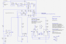
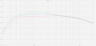 VENTED BOX like Sony SA-W2500 with para-inductance (frequency response).png20.5 KB · Views: 380
 -
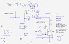 VENTED BOX like Sony SA-W2500 with para-inductance (schematic).png32.4 KB · Views: 400
 -
Sony subwoofer SA-W2500.zip446.1 KB · Views: 81
Yes, setting bridge balance using DC or very low frequency and looking for the null or minimum in the bridge output is an easy way to do it in practice. In Simulation, since you know the exact values of the sense resistor and Re, you can just set the values of the resistors in the opposite bridge arms to have the same ratio.Ah, in days of yore (and by theory) you'd want to balance for DC, frequency of lowest impedance point, or glued voice coil when the speaker is connected! Does that make sense?
Once the bridge is balanced, then you can adjust loop gain. This is adjustment is best performed with the feedback loop broken so you are measuring open loop gain…so no oscillation or smoke. In both practice and simulation, you increase loop gain as much as possible while keeping the measured or simulated phase margin > 30deg. Then, close the feedback loop and measure performance.Today, you could use THD or 10dB before oscillation or 5 dB before smoke comes from the voice coil.Not actually do-able in a simulation I suppose, but just wonderin'.
Analog Servo Sub - Open Loop Measurement
Circuit looks goodLTspice simulation done. Is it okay like this?
 , and spice modeling of loudspeaker and enclosure most impressive
I’m not sure what your goal is, but if you are trying to match performance of the SA-W2500 you will need to use the correct values for R204 = 220, and R704 = 1.2K. These changes will lower the loop gain by about 1.7x from what you currently have and then simulation will match better with actual performance.
What woofer and enclosure parameters are you using?
I posted the T/S parameters and box dimensions I measured earlier in the thread here:Post#211.
I see now that I call out box tuning of 40Hz, but didn’t give dimensions of port.
My recollection was that it was about 65mm in diameter and 240mm long.
Attached are the Thiele - Small parameters of some 25 cm woofers. I'll try simulating the Sony design with one of those, trying to get a 35 Hz to 120 Hz frequency response, in a 3 dB corridor.
Playing with R202 value reveals the effect of the motional voltage extraction feedback. Increasing R202 value gradually from 0.47 k ohm to 4.7 k ohm corresponds to gradually lowering the feedback.
Sony could have added a woofer excursion protection. Consider X202b output. This is the motional voltage, aka cone speed. Send such voltage into a 3 Hz lowpass filter (aka integrator). The lowpass filter output corresponds to the instantaneous cone excursion. Hook a full-wave rectifier. Hook a peak detector with short attack time and long release time. Add a difference amplifier having a certain voltage gain, one leg is the voltage coming from the detector, and the other leg is a DC voltage corresponding to the maximum allowed excursion. The difference amplifier output could progressively drive a vactrol (LED + LDR combination) or a JFET, acting as input attenuator.
Attachments
Piezo accelerometer substitute for back EMF in Sony W2500?
I started reading this thread a couple of weeks ago about motion feedback so I went out and purchased some Sony W2500's, assorted PZT piezo ceramics, and ADXL377 (+/- 200 g's) analog output to begin testing. This is all new and unfamiliar territory for me, but I think it should be possible to substitute the piezo output for the back emf output (with some minor op amp modifications in the circuit already present in the Sony amp board to extend the bass further. I plan to use the modified subwoofers in an in and infinite baffle system. I can tell you that taking the sony woofer out of its box and putting it in a much larger box (using the original amp / feedback) vastly improves the sound. Additionally, I originally thought the Sony mica infused cone woofer was going to be cheap but it is quite lightweight and rigid.
The first part of my efforts here is just to get my bearings and in the ball park of outputs, mounting, etc. Below is a brief progress report on the piezo / accelerometer pilot studies I have been working on. I know there are lots of points to critiques however I just want to get my hands on this concept and try to implement it into something useful.
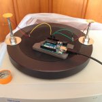
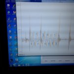
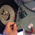
In the first pic, I have attached (poorly affixed as I do not want to alter the the very solid and flat dust cover or driver yet) piezo and ADXL377 (under the tape). When I handle the piezo (before fixing to dust cover) I feel this thing is sensitive and that flexing the brass plate has a significant effect on the voltage output as much as simulating on / off pressure / rarefraction. I think the voltage output of the piezo can be much greater than the ADXL (about 7millivolts/g). Capturing a good scan on the arduino software is not going to work and I will probably buy an oscilloscope. I understood a priori how critical the fixation of the piezo would be to the driver but underestimated this. I also discovered how critical the orientation of the piezo is with respect to voltage output.
My big concern is when looking at the one photo I have found of Genesis' piezo mounting on the voice coil, I think they have it backwards...or wrong..the pic shows the piezo mounted on its brass plate which makes no sense to me. I would think the small brass plate is the seismic mass that is required to effect a pressure differential during acceleration? This is why I have them mounted this way in the first pic although I think it is wrong..unless the mounting surface under the brass plate is so small that it allows the brass plate to flex which in turn induces a voltage difference in the piezo? But then, the piezo ceramic would have to be cut so the voltage / force is in the radial direction?
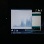
In the poor scan shown, the 60hz sine wave output is being shown from the piezo. Attaching a weight (nut) increases output but again, I think the nut should be on the other side. The battery is there in series with the piezo in the circuit to be able to capture the negative wave of the sine wave. I was trying to compare output from two piezos and the ADXL but not satisfied with my set up, but at this point I began to think the piezo was superior device to use for this application vs. the ADXL.
Next pic, by complete serendipity (my career based on it Ha!) I happened to have a sieve shaker (60 Hz) very strong so a couple of pounds on top wont matter..and by some miracle, it has a g-force read out. So I made some short bolts / threaded rod, and to that mounted another bolt to which is attached a piezo...and I have two spots for piezos so I mounted one very securely as per the genesis servo subwoofer orientation and the other the way I think it should be (ceramic side fixed, brass plate free to move)..then I added a seismic mass to it (tape roll affixed to the very rim of the brass plate) - sensitivity up 20-50 fold! Looks like I can get ~1 volt out at 0.2 g's. which will be way more than ADXL and piezo seems much quieter vs ADXL noise-wise. The increasing output shown in the second graph is because when the instrument is powered on is slowly ramps up its g-force.
I need to play around more but I am getting a feel for things. Will need some sort of oscilloscope. I also realize I am rediscovering the wheel here with regard to piezo performance but reading all the tech documents and my understanding how the piezo works would not have led me to think that flexing the brass plate would have such a profound influence on the output.
Any comments or thoughts appreciated...I know a lot of points to critique now but I am learning some things.
I started reading this thread a couple of weeks ago about motion feedback so I went out and purchased some Sony W2500's, assorted PZT piezo ceramics, and ADXL377 (+/- 200 g's) analog output to begin testing. This is all new and unfamiliar territory for me, but I think it should be possible to substitute the piezo output for the back emf output (with some minor op amp modifications in the circuit already present in the Sony amp board to extend the bass further. I plan to use the modified subwoofers in an in and infinite baffle system. I can tell you that taking the sony woofer out of its box and putting it in a much larger box (using the original amp / feedback) vastly improves the sound. Additionally, I originally thought the Sony mica infused cone woofer was going to be cheap but it is quite lightweight and rigid.
The first part of my efforts here is just to get my bearings and in the ball park of outputs, mounting, etc. Below is a brief progress report on the piezo / accelerometer pilot studies I have been working on. I know there are lots of points to critiques however I just want to get my hands on this concept and try to implement it into something useful.
In the first pic, I have attached (poorly affixed as I do not want to alter the the very solid and flat dust cover or driver yet) piezo and ADXL377 (under the tape). When I handle the piezo (before fixing to dust cover) I feel this thing is sensitive and that flexing the brass plate has a significant effect on the voltage output as much as simulating on / off pressure / rarefraction. I think the voltage output of the piezo can be much greater than the ADXL (about 7millivolts/g). Capturing a good scan on the arduino software is not going to work and I will probably buy an oscilloscope. I understood a priori how critical the fixation of the piezo would be to the driver but underestimated this. I also discovered how critical the orientation of the piezo is with respect to voltage output.
My big concern is when looking at the one photo I have found of Genesis' piezo mounting on the voice coil, I think they have it backwards...or wrong..the pic shows the piezo mounted on its brass plate which makes no sense to me. I would think the small brass plate is the seismic mass that is required to effect a pressure differential during acceleration? This is why I have them mounted this way in the first pic although I think it is wrong..unless the mounting surface under the brass plate is so small that it allows the brass plate to flex which in turn induces a voltage difference in the piezo? But then, the piezo ceramic would have to be cut so the voltage / force is in the radial direction?
In the poor scan shown, the 60hz sine wave output is being shown from the piezo. Attaching a weight (nut) increases output but again, I think the nut should be on the other side. The battery is there in series with the piezo in the circuit to be able to capture the negative wave of the sine wave. I was trying to compare output from two piezos and the ADXL but not satisfied with my set up, but at this point I began to think the piezo was superior device to use for this application vs. the ADXL.
Next pic, by complete serendipity (my career based on it Ha!) I happened to have a sieve shaker (60 Hz) very strong so a couple of pounds on top wont matter..and by some miracle, it has a g-force read out. So I made some short bolts / threaded rod, and to that mounted another bolt to which is attached a piezo...and I have two spots for piezos so I mounted one very securely as per the genesis servo subwoofer orientation and the other the way I think it should be (ceramic side fixed, brass plate free to move)..then I added a seismic mass to it (tape roll affixed to the very rim of the brass plate) - sensitivity up 20-50 fold! Looks like I can get ~1 volt out at 0.2 g's. which will be way more than ADXL and piezo seems much quieter vs ADXL noise-wise. The increasing output shown in the second graph is because when the instrument is powered on is slowly ramps up its g-force.
I need to play around more but I am getting a feel for things. Will need some sort of oscilloscope. I also realize I am rediscovering the wheel here with regard to piezo performance but reading all the tech documents and my understanding how the piezo works would not have led me to think that flexing the brass plate would have such a profound influence on the output.
Any comments or thoughts appreciated...I know a lot of points to critique now but I am learning some things.
Attachments
An audio frequency sieve shaker. What a clever find!
Looking forward to learning what you are finding, even the dead ends. Thanks for posting.
B.
Looking forward to learning what you are finding, even the dead ends. Thanks for posting.
B.
Piezo accelerometer substitute for back EMF in Sony W2500 - Part 2.
First - A big thank you to bentoronto and bolserst for sharing their knowledge and and tips.
I received my oscilloscope this week and have some data to show. All this is new / first time for me from analyzing piezo's to using oscilloscope, to making circuits, etc. so lots to critique. I do think I have reasonable data here.
1. Direct readings from piezo
Shown are the piezo affixed to the sturdy dust cover of the Sony W2500 woofer. Mounted / supported from edge of brass ( I think this one is actually aluminum) plate with added seismic mass of a few grams and small surface mounting area at the base to allow for flexing. Not how I would do it in future as the mass it more than needed and sensitivity too high, but it is what I had and is working. First pic (if I get these uploaded in the correct order) is from ipod touch output signal generator at 125Hz. Note the waveform and frequency analysis reading (also 125Hz exact) on the oscilloscope - looks very good, almost too good like I have the ipod touch going directly in the scope (I don't).

Next pic - 60Hz, expanded scale to try to get just one waveform. One can see some harmonics there, but I think it probably is due to the wires acting as strings..the one set of wires is too stiff...need something really fine and flexible.

2. Waveforms vs Frequency output from piezo - snapshots
Some snapshots from oscilloscope - sinewave output from signal generator in ipod touch (BLUE trace), simultaneous read from piezo (YELLOW trace).
Note the scale and output of piezo as a function of frequency -output increases to around 60 Hz then tapers off above that I am guessing in part due to cross over in Sony circuit? Also note shift in waveform relative to input wave as a function of frequency. Note the strength of the output from the piezo (different scale settings for input and output)


My thoughts...the waveform from the piezo compares very well to the input signal (at the very low volumes tested). Is the motion feedback from the Sony amp this good or am I not picking up the nuances of the differences between the input and output signal?
3. Output from piezo into buffering op amp
I made a simple circuit using TI TL074 op amp and fed the output from the piezo into it and looked at the output. I think it is just a buffering circuit but it seems to be attenuating the output and introducing noise. I am getting these spikes of noise which are worrisome - see figure. Any ideas what is causing this noise..is it the op amp? I dont think it is from the +/- 12V power supply as its output seemed pretty clean.


Next planned is introducing the integrator circuit...
First - A big thank you to bentoronto and bolserst for sharing their knowledge and and tips.
I received my oscilloscope this week and have some data to show. All this is new / first time for me from analyzing piezo's to using oscilloscope, to making circuits, etc. so lots to critique. I do think I have reasonable data here.
1. Direct readings from piezo
Shown are the piezo affixed to the sturdy dust cover of the Sony W2500 woofer. Mounted / supported from edge of brass ( I think this one is actually aluminum) plate with added seismic mass of a few grams and small surface mounting area at the base to allow for flexing. Not how I would do it in future as the mass it more than needed and sensitivity too high, but it is what I had and is working. First pic (if I get these uploaded in the correct order) is from ipod touch output signal generator at 125Hz. Note the waveform and frequency analysis reading (also 125Hz exact) on the oscilloscope - looks very good, almost too good like I have the ipod touch going directly in the scope (I don't).
Next pic - 60Hz, expanded scale to try to get just one waveform. One can see some harmonics there, but I think it probably is due to the wires acting as strings..the one set of wires is too stiff...need something really fine and flexible.
2. Waveforms vs Frequency output from piezo - snapshots
Some snapshots from oscilloscope - sinewave output from signal generator in ipod touch (BLUE trace), simultaneous read from piezo (YELLOW trace).
Note the scale and output of piezo as a function of frequency -output increases to around 60 Hz then tapers off above that I am guessing in part due to cross over in Sony circuit? Also note shift in waveform relative to input wave as a function of frequency. Note the strength of the output from the piezo (different scale settings for input and output)
My thoughts...the waveform from the piezo compares very well to the input signal (at the very low volumes tested). Is the motion feedback from the Sony amp this good or am I not picking up the nuances of the differences between the input and output signal?
3. Output from piezo into buffering op amp
I made a simple circuit using TI TL074 op amp and fed the output from the piezo into it and looked at the output. I think it is just a buffering circuit but it seems to be attenuating the output and introducing noise. I am getting these spikes of noise which are worrisome - see figure. Any ideas what is causing this noise..is it the op amp? I dont think it is from the +/- 12V power supply as its output seemed pretty clean.
Next planned is introducing the integrator circuit...
The spikes and noise might be just picked up in test wiring. Almost inevitable at breadboard stage. Any wiring links having higher impedance and need shielding?
To see low levels of distortion from an amp on a scope, the usual logic is put the signal through a filter to remove the basic frequency. So whatever makes it through the filter is distortion and noise in the amp.
But the distortion of a cone driver ought to be visible if you closely superimpose it on the driving signal (in which case, it doesn't matter how clean the driving signal is since you are only interested in the visible superimposition to the output signal).
For a driver, a square signal or a non-infinite pulse can be revealing. When you pump in a square wave signal of say, 100 Hz, the device under test would have to be perfect 10-1000 Hz to pass it perfectly. But if you use a 100 Hz signal on a speaker, you would never get a great (or even a good) square wave output... but it would still reveal much about how the speaker is handling the signal.
Likewise for a pulse which will send bass-reflex speakers (or unhoused drivers) into paroxysms of rumble visible on the scope. BTW, listening to how speakers play pulses, undefined as that signal is, dramatically reveals to anybody's ear the benefits of how motional feedback controls speakers. A lot more dramatic than music as a test stimulus. I wonder if bolserst can recall impulse listening tests of his own?
Another test is when you push the system beyond its range. The sensor or driver might get there first! But if the driver is running out of excursion (easiest done at low freq to save your ears and easiest to get driver movin' at resonance). If your sensor is still linear when the driver starts to bottom-out, you'll see fireworks on your screen.
iPod as a signal source. Umm, dunno. On the other hand, any time I've double-checked my test set ups (as you have to do, of course), the analog signal coming out of my Mac laptop headphone jack has been clean beyond anything I can measure reliably.
Moving forward. But with bench R&D like this good stuff, many a hazard along the path.
Ben
Last edited:
Bentoronto - "Paroxysm of rumble" - well stated!
I think it is reasonable to use the ipod touch / iphone 5th gen and newer as frequency generators as both have very high quality audio output and reviews / measurements comparable / superior to many high end DACs.
Is it possible to bypass the motion feedback in the Sony amp? this way I could look at the output from the Piezo with and without MFB. If my limited understanding is correct, it seems like shorting out the motion feedback resistor would not work as this would send the system into overdrive as it (no voltage difference across the 0.22 ohm resistor implies the cone is mot moving thus more power from amp required then poof ! ? So how to bypass the MFB so I can get measurements?
Hombre - you're welcome!Addendum: Thanks also to Gnobuddy for sharing his prior piezo experience with me.
I recommend removing your "seismic mass". You gain three things: wider sensor bandwidth (very important!), improved sensitivity of the woofer, and reduced sensitivity from the piezo (you mentioned the piezo was too sensitive.)
For a negative feedback loop to remain stable and have a decent amount of negative feedback, you have to have a wide bandwidth. My target was 20 dB of negative feedback, and in the end I managed 18 dB, with complete stability.
To get this far, the piezo+woofer system had be massaged until there were no mechanical resonances below 1 kHz. I would have liked to go higher in frequency, but I could not - the woofer itself had a nasty spike in it's transfer function at that frequency, presumably due to cone breakup or something like that.
I managed to get the first piezo resonance considerably higher (several kHz, I don't recall exactly). In this way, the overall system was not limited by the piezo, but only by the woofer's own bandwidth.
That's the outcome you want, as we're trying to improve the speaker, not drag it down with a poor quality sensor!
If the bandwidth/stability/amount of feedback issue isn't clear, you might look up some old references on compensating op-amps for stability (from the days before they came pre-compensated), or just read up on negative feedback in audio amps, or find an introduction to analog servo and control-system design using op-amps (that's what MFB is!) Please get your information from an actual engineering textbook, not some audiophool nonsense website! 😀
By the way, I am concerned about your piezo system, mounted on what appears to be a rather thin and floppy dust-cap. The mass of the piezo sensor and floppiness of the dust-cap will create a mechanical resonance at quite a low frequency, and that will severely limit your servo'd bandwidth. If the piezo/dustcap has a mechanical resonance at 100 Hz, for example, your MFB speaker will have an upper frequency limit of less than 100 Hz. Not very useful!
What you want is a very rigid connection between the voice coil former, and the piezo sensor - no flex at all between those two. As stiff as possible, which is another way of saying that the fundamental mechanical resonance frequency is moved as high as possible.
One more comment: in a motional feedback system, if the feedback ever becomes unstable (starts oscillating), Very Bad Things (TM) happen: deafening noise that might (literally) damage the hearing of anyone nearby, a high chance of a burned-out woofer, and maybe a burned-out power amplifier too. 😱
So stability is all-important. The whole thing must remain stable even if the woofer coil is driven partway out of the gap (which means the open-loop gain of the whole system will fall, so you can't use conditionally-stable servo loops; it must be an unconditionally stable design). It must remain stable even if the power amplifier clips. It must remain stable when the temperature of the speaker and piezo change, from a cold winter day to a hot summer one.
In my case, the piezo fed into a servo board that had the appropriate circuitry to "read" the piezo, and provide loop-shaping and phase-shaping for stability. The power amp also plugged into the same board, so the piezo output was appropriately mixed in with the external audio input (to create the negative feedback loop.)
Because of concerns about those previously mentioned Bad Things (TM), during development and early testing, I never closed the feedback loop without first making frequency and phase measurements of the entire system (from audio input to piezo feedback signal.)
After each of those early initial measurements, I would modify the loop gain and phase shaping on my piezo/servo board as necessary to get rid of any problem areas. Ideally, you want to keep phase shifts between +/- 90 degrees over the entire frequency range where overall gain is greater than unity; this ensure you never meet your oscillation condition, and have a nice big phase stability margin as well. Remember, stability of the servo loop is all-important!
Only when my open-loop measurements showed that the conditions for loop stability were met, would I close the (feedback) loop. I did not want to be the one whose hearing was destroyed by an out-of-control 100-watt power amplifier, nor the one who destroyed my employer's precious prototype woofer!
In hindsight, it would probably be best to use a low-powered power amp for initial testing. A wildly oscillating 1-watt power amp will do a lot less damage than a 100-watt one! Just make sure the 1-watt amp is a good quality one, DC-coupled to the speaker, wide bandwidth, etc. There are a number of low-power analog class AB chip amps that would probably fit the bill.
-Gnobuddy
Thank you for your informative posts and suggestions.
Although I liked it, the piezo with the seismic mass has been removed - the added weight, sensitivity and complexity (one more part to potentially fall off or lever / pry off the ceramic PZT layer does not seem necessary. The dust cap on the Sony W2500 is flat and fairly sturdy - I can push the equivalent of ~300 grams with my finger (surface area less than piezo) without noticeable indentation which equates to at least 20g's based on the piezo weight and surface area and I am testing at low volumes so I think this is okay (mounting on dust cap) for now.
Noise spikes really bothering me from my breadboard set up so went back to running the piezo directly into oscilloscope just to get some comparison data that I think is tenable.
I collected some data simultaneously from input signal from frequency generator (36 Hz) and the output from the piezo mounted to the dust cap in the scope and exported to excel. I manipulated the piezo waveform to overlap as close as possible to the input by adjusting the phase (shifting x-axis values) and amplitude (scaling y-values). My thinking is the difference between the two waveforms would give me an indication of how much correction would be needed from a piezo based MFB. This is with the native Sony MFB active (it would be good if I know how to bypass the internal MFB then have a great comparison / contrast).
Anyhow..here is the data - 36 Hz input.
Figure 1. Raw Data: 36 Hz Input (BLUE trace) and Piezo Output (YELLOW trace)

At first glance, I think this looks quite good. But also makes me wonder if there is much room for improvement. Maybe at higher volumes things would look significantly different?
Figure 2. 36 Hz Input (BLUE trace) and Scaled Piezo Output (RED trace)

Superimposing the waveforms as close as possible showing the difference between the waves - subtle but as expected the woofer acceleration (indicated by subtle difference in slope of the sine waves) is just a bit below that of the input signal.
Figure 3. 36 Hz Input (BLUE trace) and Scaled Piezo Output (RED trace) - Zoomed in.
No too big a difference...is this the efficacy of the Sony MFB at work here? The waveforms match quite well.
Thoughts?

Although I liked it, the piezo with the seismic mass has been removed - the added weight, sensitivity and complexity (one more part to potentially fall off or lever / pry off the ceramic PZT layer does not seem necessary. The dust cap on the Sony W2500 is flat and fairly sturdy - I can push the equivalent of ~300 grams with my finger (surface area less than piezo) without noticeable indentation which equates to at least 20g's based on the piezo weight and surface area and I am testing at low volumes so I think this is okay (mounting on dust cap) for now.
Noise spikes really bothering me from my breadboard set up so went back to running the piezo directly into oscilloscope just to get some comparison data that I think is tenable.
I collected some data simultaneously from input signal from frequency generator (36 Hz) and the output from the piezo mounted to the dust cap in the scope and exported to excel. I manipulated the piezo waveform to overlap as close as possible to the input by adjusting the phase (shifting x-axis values) and amplitude (scaling y-values). My thinking is the difference between the two waveforms would give me an indication of how much correction would be needed from a piezo based MFB. This is with the native Sony MFB active (it would be good if I know how to bypass the internal MFB then have a great comparison / contrast).
Anyhow..here is the data - 36 Hz input.
Figure 1. Raw Data: 36 Hz Input (BLUE trace) and Piezo Output (YELLOW trace)
At first glance, I think this looks quite good. But also makes me wonder if there is much room for improvement. Maybe at higher volumes things would look significantly different?
Figure 2. 36 Hz Input (BLUE trace) and Scaled Piezo Output (RED trace)
Superimposing the waveforms as close as possible showing the difference between the waves - subtle but as expected the woofer acceleration (indicated by subtle difference in slope of the sine waves) is just a bit below that of the input signal.
Figure 3. 36 Hz Input (BLUE trace) and Scaled Piezo Output (RED trace) - Zoomed in.
No too big a difference...is this the efficacy of the Sony MFB at work here? The waveforms match quite well.
Thoughts?
I'm sure your testing (once you have actual feedback in place) will tell you a great deal....I can push the equivalent of ~300 grams with my finger (surface area less than piezo) without noticeable indentation which equates to at least 20g's based on the piezo weight and surface area and I am testing at low volumes so I think this is okay (mounting on dust cap) for now.
Meantime, there are a few different ways to look at the system. One is to look at the fundamental mechanical resonance frequency of the piezo (sensor) mass. The physics of this type of mechanical resonance tells the answer will work out to be of the form (resonant frequency = square root of [stiffness/mass])
As you drive the speaker/sensor system through the resonant frequency (from just below to just above), there will be 180 degrees of phase shift from the piezo sensor alone (plus some more from the speaker itself). This much phase shift means you are guaranteed that your negative feedback turns into positive feedback somewhere in this frequency interval. That means the servo cannot remain stable.
The short version is what I mentioned before - the bandwidth of a practical, stable MFB system will always be *less* than the lowest mechanical resonance frequency of your piezo sensor. Stiff and light sensors are a must for acceptable servo bandwidth...
Since you mentioned "g's" of acceleration, it's interesting to make a quick estimate of this, too. When the amp drives current through the voice coil, the force (in Newtons) it generates is equal to B x L x i, where "B x L" is the "BL product" you can usually find in the speaker specifications, and "i" is the voice coil current in amps.
This is the force; Newton's famous f=ma tells us the corresponding speaker cone/voice coil acceleration:
a = f/m = BLi/m
(where "m" is the moving mass of the speaker, also usually found in the speaker specifications).
Putting some numbers to it, if BL is 6 Tesla-metres (a figure I remember from some woofer I looked at once), and the moving mass is 50 gm, and you run 10 watts RMS into a 4-ohm voice coil (peak current is 2.24 A), you get a peak cone acceleration of about 268 metres/second squared.
1 "g" is about 9.8 metres/second squared, so that translates to a voice coil / speaker cone/ piezo sensor acceleration of about 27 g's - and that's from only 10 watts RMS input!
The "g" forces are proportional to voice coil current; so at 40 watts RMS, they go up to 54 g's.
And a 10-gram piezo sensor at 54 g's exerts an inertial force of 540 grams on its mounting...much more than the 300 gm you mentioned.
These are only "in the ballpark" estimates, especially since I don't know the actual BL product of your woofer, or its moving mass.
Still, I think there's quite a high chance that you will indeed find your piezo mounting is not stiff enough. But I don't want to spoil your fun experimenting, or annoy you by repeating myself too many times. (I'm just trying to be helpful, but I know that too much helpfulness can become annoying too!)
Good luck, and I hope your project has a successful conclusion!
-Gnobuddy
Gnobuddy -
Thank you for your input, insight and lucid post - I appreciate the real world examples you provided to help give a meaning to these parameters that 'resonated' with me, deepening my understanding. My current set up is just temporary, volumes / cone excursion are low, piezo weight is ~ 2 grams and the output waveform looks pretty good so far so I think I am okay. I agree with everything you have stated and understand your concerns about the piezo mounting - sort of like a small spring (piezo) mounted on the end of another spring (woofer). I appreciate your efforts to inculcate how critical the interplay between the mechanical and electrical resonance and will be mindful of these admonitions when I get to the final prototype.
Before I began this project, in my naïve mind's eye I envisioned how I would approach this. I imagined two sine waveforms - one from the preamp input signal and one output from the piezo, run them through a comparator / difference op amp and then along to the amp and poof servo feedback in a can. I was aware of phase shifting but didn't appreciate its importance until I saw it on the scope - the heavy dependence of the amplitude and phase of the output of the piezo as a function of frequency. Then it hit me - this must be why there is an 'integrator' op amp in these servo circuits...or maybe it should be a differentiator - who cares what the amplitude and phase is if all I want to do is correct for the instantaneous slope of the output vs input? Should be possible?
Further, not that I have the knowledge or capability of implementing this, but I can also see now how converting the piezo output to a digital signal then using some math to transform / process this signal, easily correcting for the phase and amplitude shifts throughout the frequency spectrum. Just some random musings from a newbie.
Bentoronto - See above post on superimposing waveforms. Looks pretty good to me at these very low levels. Spikes on signal from op amp are holding me back from adding next step in circuit. Not sure what to do about it other than try to cobble solder things together without PCB.
I understand about trying the square wave as the acid test. Supposedly, the Genesis Servo Bass loudspeakers are the only speaker that can in fact reproduce a square wave.
I understand about trying the square wave as the acid test. Supposedly, the Genesis Servo Bass loudspeakers are the only speaker that can in fact reproduce a square wave.
You're exactly on the right track with those thoughts. 🙂...heavy dependence of the amplitude and phase of the output of the piezo as a function of frequency. Then it hit me - this must be why there is an 'integrator' op amp in these servo circuits..
Down around it's fundamental resonance frequency, a speaker itself acts as a second-order high pass filter. If you had a perfect piezo sensor (or other accelerometer) mounted to the voice coil, it would accurately reproduce that second-order high pass filter response.
Here's what that means: well below the resonance frequency, you have 180 degrees of phase lead. If the speaker was perfect (no cone break up), then you'd have zero phase shift at all frequencies well above the resonance frequency.
And even in this ideal world (perfect speaker, perfect sensor), you already have a problem: no matter what you do, 180 degrees of phase shift in the speaker+piezo system means you will have positive feedback either below the speaker resonance, or above it. So you can choose between either a loud uncontrollable howl below the speakers Fs, or above it!
There is a simple solution, however: add a steady 90 degree phase lag through the entire frequency range. With this change, the 180 degree phase lead of the speaker below Fs now becomes only a 90 degree lead. Meantime, the zero phase shift above resonance, now becomes a 90 degree lag.
90 degrees of phase shift inside a negative feedback loop is okay - the loop remains stable. So, if you had an ideal speaker and an ideal sensor, you'd now have a well-behaved and quite tractable system, waiting for you to add some nice stable negative feedback.
Unfortunately, in practice, as you go higher in frequency, you'll inevitably get extra phase-shifts from cone break-up, and piezo sensor break-up. Each of those resonances will add 180 degrees of total additional phase shift, and 90 degrees of it will be lag at frequencies above resonance. Added to the 90 degrees of lag we already have, there will immediately be 180 degrees of total phase shift. So even one single cone-break up mode, or piezo resonance, is very likely to make our MFB servo system go violently unstable.
You can't avoid these additional phase shifts from speaker cone break-up. So how can you keep the MFB system stable? You have to reduce the gain of the system to less than unity (1.0) by the time the phase shift exceeds 180 degrees. In this way, you avoid the self-oscillation condition.
So now the beginnings of the MFB system recipe are starting to become clear: you want to add 90 degrees of phase lag to the entire frequency range of the MFB, and you want to roll off the open-loop gain of the system, so that it is below unity by the time you get to the first cone break-up mode.
What circuit adds 90 degrees of phase-shift, and also rolls off the high frequency response? Yup, an integrator!
So there's your starting point. You pretty much must add an integrator in your servo loop - the signal from the piezo sensor must go through an integrator before it is mixed (subtracted) from the incoming audio signal.
The integrator alone is enough to give you a working MFB system, but it may not be as good as you'd like; in particular, you will quite likely find out that speaker cone break-up modes, and/or piezo sensor resonances, will limit how much "F" you can have in your MFB system.
And that's the point at which the hard work begins - to make any headway with that battle, you have to make the accelerometer as nearly flawless as possible, you have to move cone break-up modes as high in frequency as possible, and you may have to play some additional clever tricks in the servo loop frequency and phase shaping (above and beyond the basic integrator).
But the starting point for it all is the integrator. Make sure the integrator's working frequency range extends far below the woofer resonance (fs), and that it continues to work far above. For example, if the woofer has a 40 Hz resonance, you'd want the integrator to work accurately from at least 4 Hz to at least a few kHz.
I'll say up front that you'll probably find that the 4 Hz end will be quite challenging - it is hard to make a piezo sensor work well at very low frequencies!
-Gnobuddy
Great stuff. I was on vacation, but gnobuddy sure knows things I don't (and maybe vice versa).Bentoronto - See above post on superimposing waveforms. Looks pretty good to me at these very low levels...I understand about trying the square wave as the acid test. Supposedly, the Genesis Servo Bass loudspeakers are the only speaker that can in fact reproduce a square wave.
With waves superimposed that way, even little nice-looking departures from matching represent big distortion. Run both signals through an RTA like in REW and see.
Square-wave or impulse signals need a few octaves bandwidth to pass, still you can feed it to your speaker, even through a crossover. Just a matter of what to expect on the scope. With MF, watching the drive signal is great fun because you will see monumental voltage efforts to correct the massive (relative to air) cone inertia (both on onset of pulse and on offset)... which means the MF is working properly.
While it is conceivable that a cone could sort of trace a square wave reasonably well, what a mic picks up is awful looking.
As far as sound to your ear goes, like with cone motion, you can't expect a chirp from a sub playing an impulse (or whatever a square wave might sound like if played in Disney's Fantasia movie). But MF will grasp increase the crispness (speed?) of the sound.
Is the ACM-01 accelerometer your next experiment?
Ben
Last edited:
Bentoronto -
Right now, the ACH-01 accelerometer is not on my to do list. Here are my reasons:
1. Additional complexity due to ACH-01 needing a power supply.
2. Heavier than the piezo (at least compared to the piezos I have been using).
3. I think sensitivity of ACH-01 (~9 millivolts/g) is lower than the piezo's.
4. I think I recall reading (from piratelogic?) that he struggled with using the ACH-01.
5. Not that important, but cost $60 vs $2
If I am overlooking something I would be happy to reconsider testing it. I do see the phase response of ACH-01 as a function of frequency is fairly flat. However, I think the phase shift I am seeing in the above graphs is from the crossover in the Sony amp.
RE: Feeding Square waves - would I have to bypass the internal crossover in the Sony Amp?
- Home
- Loudspeakers
- Subwoofers
- Commercial motional feedback woofer available sort of