
Andrew,Looks superbbbb and sound alike !!


Finally ready music.
Very nice!
How did you build the enclosure? Looks very professional!
Thanks.. the chassis is from an old amp that shorted out beyond repair.Very nice!
How did you build the enclosure? Looks very professional!
Saved the faulty Harman Kardon PM 645 from the bin
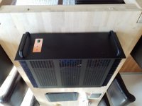
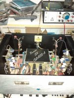
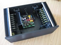
So I have been given a stereo amp that had a functioning transformer and power supply and I thought to myself why not fit it with G.Randy Slone's pro 60 amp modules. This time I fabricated proper pcb's using the toner transfer method and it worked suprisingly well after I figured out how to's. I have added a turn-on delay, dc protection and 75 deg C thermal switch for a peace of mind.
So I have been given a stereo amp that had a functioning transformer and power supply and I thought to myself why not fit it with G.Randy Slone's pro 60 amp modules. This time I fabricated proper pcb's using the toner transfer method and it worked suprisingly well after I figured out how to's. I have added a turn-on delay, dc protection and 75 deg C thermal switch for a peace of mind.
Attachments
So I have been given a stereo amp that had a functioning transformer and power supply and I thought to myself why not fit it with G.Randy Slone's pro 60 amp modules. This time I fabricated proper pcb's using the toner transfer method and it worked suprisingly well after I figured out how to's. I have added a turn-on delay, dc protection and 75 deg C thermal switch for a peace of mind.
 ..really nice work, hard to see it's DIY,
Hi Chris,
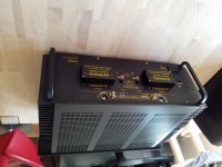
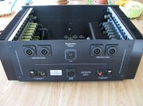
unfortunately, now that it has been modified, it is not so simple to remove the panel as it once used to be. There is not much to see other than 4 output transistors, 2sc3281/2sa1302 and some wires. They are positioned in the same place as original ones.
I design everything to have "ease of servicing" in case repairs ever need to be made.
So far, things I've built since the 1980's are still in perfect shape, no servicing required.
Hi wiseoldtech,
That's the part about being wise ... cause you're an old tech! You didn't age in this business without learning how to keep life simple for the future. That's called survival.
I do the same thing. Probably because I take things apart and fix them for a living.
-Chris
That's the part about being wise ... cause you're an old tech! You didn't age in this business without learning how to keep life simple for the future. That's called survival.
I do the same thing. Probably because I take things apart and fix them for a living.
-Chris
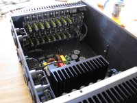
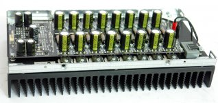
New modification A + A / B
RMS: 300 W 8 Ohm
600 W 4 Ohm
1200 W 2 Ohm
Gain coefficient: 30 dB
Dynamic range: >100 dB
Damping DC coefficient: 5000 @ 8 Ohm
Peak output current: 96 A
Nonlinear distortion coefficient: <0.01 % within the 20 Hz-20 kHz range
Frequency response: 10 Hz-200 kHz +0,-3 dB
RMS: 300 W 8 Ohm
600 W 4 Ohm
1200 W 2 Ohm
Gain coefficient: 30 dB
Dynamic range: >100 dB
Damping DC coefficient: 5000 @ 8 Ohm
Peak output current: 96 A
Nonlinear distortion coefficient: <0.01 % within the 20 Hz-20 kHz range
Frequency response: 10 Hz-200 kHz +0,-3 dB
Attachments
Last edited:
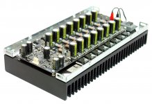
New modification A + A / B
RMS: 300 W 8 Ohm
600 W 4 Ohm
1200 W 2 Ohm
Gain coefficient: 30 dB
Dynamic range: >100 dB
Damping DC coefficient: 5000 @ 8 Ohm
Peak output current: 96 A
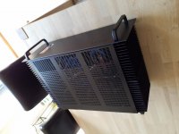
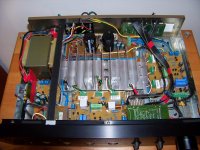
Pretty neat layout.
But where's the big power transformer?
The main filter capacitors?
I hope you don't tell me it's using some sissy SMPS.
Hi wiseoldtech,
That's the part about being wise ... cause you're an old tech! You didn't age in this business without learning how to keep life simple for the future. That's called survival.
I do the same thing. Probably because I take things apart and fix them for a living.
-Chris
Any tech or designer worth their weight would do the same.
However, I've seen some real crap over the years and wondered what drugs those designers were on.
Pretty neat layout.
But where's the big power transformer?
The main filter capacitors?
I hope you don't tell me it's using some sissy SMPS.
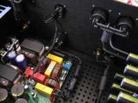
Large transformers and huge banks of capacitors remained in the last century. We use switching power supplies using PFC technology with a frequency of 400 kHz.
Therefore, large capacitance capacitors are not needed, and the amplifier is not afraid of interference, because it is made according to RF interference-proof technologies using a 4-layer printed circuit board, with power supply polygons and a separate shielding layer.
Last edited:
Easy, they never had to fix their own designs before. It's the only explanation.However, I've seen some real crap over the years and wondered what drugs those designers were on.
-Chris
- Home
- Amplifiers
- Solid State
- Post your Solid State pics here