Hi Frantisek,
Don't worry about your language being rough. Mine is worse so you are doing a lot better than I would be.
I was wondering if the copper traces on the circuit board could carry the high currents this design can deliver.
-Chris
Edit:
Thank you Max!
At times, when I want to beef up traces that I make on perfboards, or repair a damaged one, I lay a strip of de-soldering braid, then saturate it with solder along the strip.
That then can carry quite a few amperes if need be.
DUMMY LOAD
Not fully completed dummy load. Two independent sections. Big resistors are ARCOL 8R/200W, the others are from ebay, 4R/100W (do you see the difference ? ) I added two RCA monitor ports, one is raw output, the second one is attenuated by factor 30x (4x parallel 6k8/56R+protecting zeners).
Not fully completed dummy load. Two independent sections. Big resistors are ARCOL 8R/200W, the others are from ebay, 4R/100W (do you see the difference ? ) I added two RCA monitor ports, one is raw output, the second one is attenuated by factor 30x (4x parallel 6k8/56R+protecting zeners).
Attachments


very nice - looks very good - i also think about that + dividers - so thd and fft can be measured by the sound card - 1w, 5w, 10w, and 50 w
I got Aleph Mini but not Mini going.
Got 27.6vdc rails. Had 20watts last time I checked but done mods to the board and Pay since. Good to finally have both channels going at the same time. Sounds great. I'm pretty happy with it. My father in law already wants me to make him one.

.jpg")

Got 27.6vdc rails. Had 20watts last time I checked but done mods to the board and Pay since. Good to finally have both channels going at the same time. Sounds great. I'm pretty happy with it. My father in law already wants me to make him one.
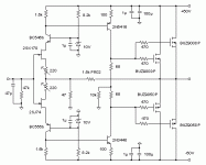
Seven years ago I did my first Mosquito amplifier for test, then I liked the sound and decided to try it again. The first time I had one pair of output laterals and a voltage of +/- 35V, now I made with two pairs and +/- 50V. I use 2SK1058 / J162 for output and 2SC2911 / A1209 for drivers.
The sound is good and I'll probably try how it sounds with other bipolar transistors or 2SK216 / J79 for drivers.
I have a modified JLH69 that sounds perfect . Mosquito has a completely different sound, not in the JLH69 class but a very good option for a good home amplifier.
For now, it promises.
The sound is good and I'll probably try how it sounds with other bipolar transistors or 2SK216 / J79 for drivers.
I have a modified JLH69 that sounds perfect . Mosquito has a completely different sound, not in the JLH69 class but a very good option for a good home amplifier.
For now, it promises.
Attachments

Attachments
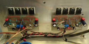
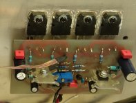
All copper traces, for high currents, are well tin-plated and connected by 16A wires.
(rails, ground, power transistor collector / emitter and OUT).
The amplifiers have been working in my gym for nearly two months.
Usually only at 10-20% power 🙂
It's a home gym, not an ibiza disco 😀
The figure shows the power supply wires used (brown, blue).
Black and green-yellow was temporary 😉

This is really really nice. How are you going to attach it to the chassis / heatsinks
2x 330W/4R for my home gym 🙂

I ran a mobile disco for years with a stripboard amp inside.
This is really really nice. How are you going to attach it to the chassis / heatsinks
Thanks.
They are only laid on heatsink yet.
Amps work like this for two months in my gym 😀
Fasten them through the 4 + 4 holes on the prisms.
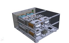
The beginning of my next huge class A mono blocks.
They will be Nelson pass class A mono blocks
drool
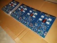
Very neat and beautiful on general purpose boards, Inko.
pl post pictures of the other/reverse side also.
pl post pictures of the other/reverse side also.
Thanks.
They are only laid on heatsink yet.
Amps work like this for two months in my gym 😀
Fasten them through the 4 + 4 holes on the prisms.
Looks great -NASA grade!All copper traces, for high currents, are well tin-plated and connected by 16A wires.
(rails, ground, power transistor collector / emitter and OUT).
The amplifiers have been working in my gym for nearly two months.
Usually only at 10-20% power 🙂
It's a home gym, not an ibiza disco 😀
The figure shows the power supply wires used (brown, blue).
Black and green-yellow was temporary 😉
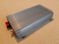
100 watt retro amp based on 1980's Maplins 225WRMS disco amplifier.
Uses easy to find modern transistors.
The heat sink drilling is fun with TO3's. I used the pcb as a drilling template.
Uses easy to find modern transistors.
The heat sink drilling is fun with TO3's. I used the pcb as a drilling template.
An externally hosted image should be here but it was not working when we last tested it.

- Home
- Amplifiers
- Solid State
- Post your Solid State pics here