The point being that you grossly overestimate what you can hear (-;?
I have an article about the challenge in the attick somewhere, I'll look it up.
Really? What's false about it? The only flaw I can think of is that it ignores linear errors like polarity inversion and roll-off. Or do you believe in inverse masking, soft sounds becoming more audible when there is loud music playing?
It's really not worth discussing these things with TB; he's got a strong tendency towards ideology and NIH (Not invented here) that gets obfuscated by his use of engineery language. Or at least prepare yourself for frustration.
")
jan.didden. Here is the link:
Quad 405 : analyse d'un schéma
QUAD 405 analysis. In Audiophile n°1, octobre 1977
Enjoy.
Quad 405 : analyse d'un schéma
QUAD 405 analysis. In Audiophile n°1, octobre 1977
Enjoy.
jan.didden. Here is the link:
Quad 405 : analyse d'un schéma
QUAD 405 analysis. In Audiophile n°1, octobre 1977
Enjoy.
Thanks, that's useful. But I was also interested in the blind testing paper as mentioned by Marcel.
Jan
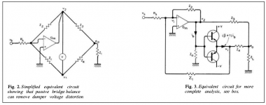
My French isn't great but it seems to me that Fig 8 is discussing a voltage amplifier, G, driving the transistors. The Quad is described by Vanderkooy and Lipshitz as using a transconductance amplifier (see below). So I am not sure what the Quinquis article is trying to show.Page 5 of Quad 405 : analyse d'un schéma
It's about the output impedance.[/IMG]
In the V & L model it can be seen by inspection that the output impedance changes when the transistors start to conduct (because they add current gain). It can be shown by simulation too. A constant output impedance being caused by using a bridge arrangement is not correct IMO.
Attachments
Definitely prepare for frustration...I don't take prisoners and I don't put up with crap regardless of who generates it. Well, most of the time.It's really not worth discussing these things with TB; he's got a strong tendency towards ideology and NIH (Not invented here) that gets obfuscated by his use of engineery language. Or at least prepare yourself for frustration.
This is an old trick that is based on a false premise. It's not a meaningful test except perhaps when extreme distortion is present. Reminds me of Hafler.
Please elaborate on the false premise. Is it like the diff of two digital files being null but they still sound different?
Thanks for trying this out. I think I need to see what your models are to comment usefully. The linear amp needs to be a transconductance amp. The amount of NFB needs to be the same in both.I made a simple model with a resistive bridge, an ideal x100 amplifier and a simple class B transistor buffer with zero bias.
The distortion at 1V peak was about 0.1% and only 3rd harmonic.
Changed to a standard negative feedback only and distortion was 0.3% 3rd and a slew of higher harmonics
An ideal output stage should have a constant output impedance. The challenge for the creators of the current damping topology was to achieve this with a class C ouput stage (chosen for not needing bias setting) delivering most of the power. The result may not be absolutely perfect but it is there and it works remarkably well since more than forty years, being appreciated by a huge amount of people.In the V & L model it can be seen by inspection that the output impedance changes when the transistors start to conduct (because they add current gain). It can be shown by simulation too. A constant output impedance being caused by using a bridge arrangement is not correct. IMO.
I do not know an amp output circuit as ingenious as the one signed by Walker and Albinson. I think they were not obsessed by the highest performances. More recent circuits prove that current dumping with output power transistors biased in class B can give an impressive linearity.
Marcel, you have a link to that paper perhaps?
Jan
No, I only have a second-generation paper copy made in the early 1990's. Of course I could scan that copy for you, if you like.
Believe me, I am looking for examples of genius in the Quad 405. Please suggest some more! I certainly agree that avoiding bias setting is a manufacturability advantage and the story that Quad told was excellent, if not genius, marketing. The 405 was never a sound quality leader but Quad sold a lot of them.An ideal output stage should have a constant output impedance. The challenge for the creators of the current damping topology was to achieve this with a class C ouput stage (chosen for not needing bias setting) delivering most of the power. The result may not be absolutely perfect but it is there and it works remarkably well since more than forty years, being appreciated by a huge amount of people.
I do not know an amp output circuit as ingenious as the one signed by Walker and Albinson. I think they were not obsessed by the highest performances. More recent circuits prove that current dumping with output power transistors biased in class B can give an impressive linearity.
I like to examine whether theory of operation claims are true.
The "current dumper" idea seems to generate a lot of disagreement.
For a start there is no feed-forward involved in the proper sense. This is very much a NFB system. In the V & L simplified model, the output impedance is the result of NFB and is not linearized by the "bridge" arrangement. Regarding distortion, the perfectly balanced bridge makes it as good as conventional feedback topology and unbalanced makes it worse. There must be another reason they chose a bridge but I haven't figured that out yet (unless it was just for marketing).
The actual circuit Quad built is very complicated. They appear to have added a number of extra components that appear to be for stability reasons. It really needs to be simulated to see what it actually does.
The current dumping principle is quite clever. Walker and Albinson had to figure out that one can make a bridge circuit with an inductor, so the low-frequency output impedance and the power losses remain low, and that the path from the dumpers through the inductor to the output could be largely cancelled by the other path with a resistor, the integrating class-A transimpedance amplifier and another resistor. In fact finite DC gain of the transimpedance amplifier can be cancelled with nonzero DC resistance of the inductor.
Although it has nothing to do with current dumping as such, the QUAD-405 DC bias loop is also interesting. I haven't seen anything like it in any other audio amplifier. It results in an almost exact second-order Butterworth high-pass response.
Although it has nothing to do with current dumping as such, the QUAD-405 DC bias loop is also interesting. I haven't seen anything like it in any other audio amplifier. It results in an almost exact second-order Butterworth high-pass response.
Hey Scott, it is remarkable what people will believe. Make sure you store your audio files on the correct type of storage device and remember that the more times you copy it the more dilute it becomes and the stronger it gets.Please elaborate on the false premise. Is it like the diff of two digital files being null but they still sound different?
QUAD subjected the QUAD-405 to subtractive tests with music, where the signal is attenuated while the distortion is not. At normal volumes you basically hear nothing when you try that. You do need good phase correction, though.
The false premise is that if you cannot hear the extracted residual distortion on its own (played through the chosen detection system, etc.) then you cannot hear it in the presence of the source music (played through the chosen replay system, etc.).
Last edited:
The false premise is that if you cannot hear the extracted residual distortion on its own (played through the chosen detection system, etc.) then you cannot hear it in the presence of the source music (played through the chosen replay system, etc.).
Makes sense to me, you can't hear something so mix it with something else you still can't hear it. False premise proven by whom, how?
Very difficult.Believe me
Sound engineers haven't emitted much criticism towards itI am looking for examples of genius in the Quad 405. Please suggest some more! I certainly agree that avoiding bias setting is a manufacturability advantage and the story that Quad told was excellent, if not genius, marketing. The 405 was never a sound quality leader but Quad sold a lot of them.
Its commercial success seems to irritate you even more than its topology.
And even more of applause.I like to examine whether theory of operation claims are true. The "current dumper" idea seems to generate a lot of disagreement.
I have studied the error correction topologies. As far as I can understand them, there is always some kind of negative of feedback in their scheme.For a start there is no feed-forward involved in the proper sense. This is very much a NFB system. In the V & L simplified model, the output impedance is the result of NFB and is not linearized by the "bridge" arrangement. Regarding distortion, the perfectly balanced bridge makes it as good as conventional feedback topology and unbalanced makes it worse. There must be another reason they chose a bridge but I haven't figured that out yet (unless it was just for marketing).
I agree with that.The actual circuit Quad built is very complicated. They appear to have added a number of extra components that appear to be for stability reasons.
Thanks for trying this out. I think I need to see what your models are to comment usefully. The linear amp needs to be a transconductance amp. The amount of NFB needs to be the same in both.
Ask yourself what the output impedance of a class B amplifier is during the switching point, it is off course very high, the output impedance of the current dumping amplifier is very low due to the class A error correction amplifier.
- Home
- Amplifiers
- Solid State
- Peter Walker and his current dumping principle