The QUAD 405 was marketed as a feed-forward topology amplifier, not using conventional negative feedback, IIRC. I am not sure if this is the same as the bridge used to produce an error signal. BTW I always wondered how those extreme bridge components (capacitor 120 pF, inductor 3 uH) could work in the lower audio range.
Really?The cuning of the dumping circuit is often looked as how the output impedance stays constant, through the feedback network, between its two states : when only the class A stage is delivering signal and when the power transistors conduct to assist it.

The QUAD 405 was marketed as a feed-forward topology amplifier, not using conventional negative feedback, IIRC. I am not sure if this is the same as the bridge used to produce an error signal. BTW I always wondered how those extreme bridge components (capacitor 120 pF, inductor 3 uH) could work in the lower audio range.
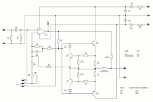
Its a matter of bridge balance. If you visualize the circuit, with Z2 being the integrator cap on the class A driver and Z4 the L from dumper output to final output, bridge balance is when Z1*Z3 = Z2*Z4 (Z1 and Z3 being resistors).
With increasing frequency Z2 (the cap) will decrease in impedance, and Z4 (the L) will increase in impedance. So the product Z2*Z4 remains constant with frequency, and since R1*R3 is resistive thus also constant with freq, bridge balance is preserved over freq.
The reason that Walker didn't use just 4 resistors for the bridge is that he would need anyway a cap across the class A for stability reasons (compensation). So that lead to the need for an L for Z4. The man was a very, very clever designer!
Anyway, there is still no agreement whether it really is a sort of feedforward or something else. Opinions differ as it is so unusual, hard to classify.
Jan
Last edited:
One of the main disadvantages which have hindered widespread acceptance is that the bridge has to be carefully balanced to get the maximum distortion null.
The 405 had a bridge which was reasonably accurate, but that meant that the distortion performance was not much different from other good amps.
So from a practical point of view, you get an amp that is comparable to other good amps, so there is no real advantage other than for marketing.
Jan
I have a 405 based circuit, basically Keith Snook mods plus complementary output stage using mjl3281/1302, I measured the track capacitance and wound the coil to match and it does sound very good, certainly a lot nicer than the naim type sound which is much too harsh for my ears. The basic Walker design is very clever and I think the reason it sounds so nice is that the speaker always sees a low impedance path due to the class A stage plus at the point the dumpers switch the class A is there to mop up some of the nasties.
Just added an LTSpice file for those interested, I did do a PCB but I am not sure how up to date it is, however if anyone feels brave you can have the kicad files. COD is for Complementary Output Dumpers and of course fish puns...
Attachments
Last edited:
From the V & L article, referring to bridge balance:
"A vital requirement that this be completely achievable in practice is that ß be constant."
🙄
Feedforward is when a predefined correction signal is fed to a later stage. This is not to be confused (although it often is) with a negative feedback derived error signal that is then fed forward.
When the Quad's output current is small such that the "dumpers" are effectively out of circuit (talking LF for the moment) then the output is driven by the class A, feedback controlled, transconductance amplifier. Which ought to sound pretty good (but there are other problems to consider even here). When the current activates the "dumper" it gets inserted into the feedback loop. I would argue, therefore, that at no point is the Quad using feedforward. A transconductance amplifier driving a load with negative feedback around it is not a feedforward system.
The upshot of this is not that Quad has a beneficial feed-forward system to reduce distortion, rather it is that having chosen to eliminate power transistor bias setting, Quad had to make some complicated cludges to try to minimize the damage caused by the conductivity gap in the output devices. Had they chosen to use bias the system would be a very much simpler one and could have sounded much better. So let's remember they deliberately chose to 'break' their output stage to make their manufacturing process cheaper and easier and the rest is tricky circuitry/smoke and mirrors to try and reverse the damage.
Credit where it is due. It kept Quad in business and was great for marketing.
Last edited:
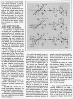
Left column, 5th scan of Quad 405 : analyse d'un schémaThe cuning of the dumping circuit is often looked as how the output impedance stays constant, through the feedback network, between its two states : when only the class A stage is delivering signal and when the power transistors conduct to assist it.
Really?
The reality is that it makes manufacturing a lot easier and perhaps field reliability (I'm not sure) but didn't break any new sound quality ground. It was easily exceeded by valve amps at the time and by conventionally biased BJT amplifiers, such as Naim's.
As far as Peter Walker was concerned, there was no ground to break; he didn't believe that well-designed amplifiers have audible distortion differences in the first place. He regularly said so in public and I think he even put out a reward for anyone who could prove him wrong in a double-blind test (which no-one managed to do). I admire his honesty about this issue; in my opinion it shows that he was an engineer first and a businessman second.
QUAD subjected the QUAD-405 to subtractive tests with music, where the signal is attenuated while the distortion is not. At normal volumes you basically hear nothing when you try that. You do need good phase correction, though.
Properties that one could regard as weak points of the QUAD-405 are the fact that it inverts, its relatively high output inductance and its roll-off below 14 Hz and above 40 kHz that already give 1 dB of loss at 20 Hz and 20 kHz. Those roll-offs are part of QUAD's philosophy, though; why amplify inaudible signals that could produce intermodulation distortion further down the chain?

If Quad current dumping is considered as having nothing of feedforward, a question rises : could Benchmark power amp AHB2 which uses its principle achieve its performances without it ?
Current dumping analysis
There was also the distortion analysis by HS Malvar in EW-WW March 1981
Malvar showed that a perfect bridge balance cannot completely null the output stage distortion as some had claimed. But it does reduce distortion lower than just using nfb.
Cheers
Left column, 5th scan of Quad 405 : analyse d'un schéma
There was also the distortion analysis by HS Malvar in EW-WW March 1981
Malvar showed that a perfect bridge balance cannot completely null the output stage distortion as some had claimed. But it does reduce distortion lower than just using nfb.
Cheers
I don't know what he was trying to say. Wasn't it a sweeping, statement that if two amps are designed well enough then you should not be able to hear a difference? "well-designed" is ambiguous.As far as Peter Walker was concerned, there was no ground to break; he didn't believe that well-designed amplifiers have audible distortion differences in the first place.
I doubt he meant that no one else's amps could sound better than his. That prejudgment would have held him back
This challenge is ambiguous in that someone has to decide what "well designed" means. I can certainly hear consistent differences between models of Krell, Naim and Lamm. Should these brands' products be considered well designed? You can also hear differences among products at different price points within a brand...so which of these products is well designed and which isn't? You see my point?He regularly said so in public and I think he even put out a reward for anyone who could prove him wrong in a double-blind test (which no-one managed to do). I admire his honesty about this issue; in my opinion it shows that he was an engineer first and a businessman second.
This is an old trick that is based on a false premise. It's not a meaningful test except perhaps when extreme distortion is present. Reminds me of Hafler. It may be Peter Walker was ignorant or it may have been a marketing device.QUAD subjected the QUAD-405 to subtractive tests with music, where the signal is attenuated while the distortion is not. At normal volumes you basically hear nothing when you try that. You do need good phase correction, though.
Interesting. I wouldn't consider these specs particularly weak. They don't look sexy on a spec sheet but that's another matter. 🙂Properties that one could regard as weak points of the QUAD-405 are the fact that it inverts, its relatively high output inductance and its roll-off below 14 Hz and above 40 kHz that already give 1 dB of loss at 20 Hz and 20 kHz. Those roll-offs are part of QUAD's philosophy, though; why amplify inaudible signals that could produce intermodulation distortion further down the chain?
Thanks. This article in French is resurrecting lost skills. I don't agree with this after simple inspection but I think a mathematical proof or simulation is demanded. The multiple feedback loops are a little complicated.Left column, 5th scan of Quad 405 : analyse d'un schéma
Attachments

Attachments
I don't know what he was trying to say. Wasn't it a sweeping, statement that if two amps are designed well enough then you should not be able to hear a difference? "well-designed" is ambiguous.
I doubt he meant that no one else's amps could sound better than his. That prejudgment would have held him back
This challenge is ambiguous in that someone has to decide what "well designed" means. I can certainly hear consistent differences between models of Krell, Naim and Lamm. Should these brands' products be considered well designed? You can also hear differences among products at different price points within a brand...so which of these products is well designed and which isn't? You see my point?
The point being that you grossly overestimate what you can hear (-;?
I have an article about the challenge in the attick somewhere, I'll look it up.
This is an old trick that is based on a false premise. It's not a meaningful test except perhaps when extreme distortion is present. Reminds me of Hafler. It may be Peter Walker was ignorant or it may have been a marketing device.
Really? What's false about it? The only flaw I can think of is that it ignores linear errors like polarity inversion and roll-off. Or do you believe in inverse masking, soft sounds becoming more audible when there is loud music playing?
Last edited:
Malvar showed that a perfect bridge balance cannot completely null the output stage distortion as some had claimed. But it does reduce distortion lower than just using nfb.
Cheers
Hi Ian,
Yes, the same point was made by Vanderkooy and Lipshitz in the analysis I linked to.
BTW Thanks for that paper. The very last column sums it up quite nicely.
Jan
Last edited:
I am afraid that is untrue.But it does reduce distortion lower than just using nfb.
Can anyone else see why?
HInt:
The stated purpose of the balanced bridge is to remove the power transistor Vbe from being fed back to the transconductance amplifier input. It does this when balanced by making the difference in voltage between the output and the feedback path to the linear amplifier independent of Vbe.
Compare this to how a conventional NFB arrangement fed by a transconductance amplifier works...
eg: An inverting transconductance amp feeding the bases of the unbiased transistor emitter followers which then connect to the speaker. The feedback is taken from the speaker output. So pretty much the same thing as the current dumper without all the bridge components.
I made a simple model with a resistive bridge, an ideal x100 amplifier and a simple class B transistor buffer with zero bias.
The distortion at 1V peak was about 0.1% and only 3rd harmonic.
Changed to a standard negative feedback only and distortion was 0.3% 3rd and a slew of higher harmonics
The distortion at 1V peak was about 0.1% and only 3rd harmonic.
Changed to a standard negative feedback only and distortion was 0.3% 3rd and a slew of higher harmonics
I have to apologize to you all and to the late Peter Walker, because what I wrote about his challenge was quite inaccurate. I read the article some 25 years ago and apparently didn't remember it accurately anymore.
Anyway, the article is "Can you hear any difference? The Quad amplifier listening test challenge described by Adrian Hope", Hi-Fi news & record review, June 1978, pages 73, 75 and 77 and it was a test between three generations of Quad amplifiers: the Quad II valve amplifier (actually three of them in parallel) and the Quad-303 and Quad-405 solid-state amplifiers. Peter Walker expected these to sound the same and was prepared to pay 5000 pounds to be proved wrong.
A panel of six people, three audio journalists, someone from the BBC and two from loudspeaker companies, listened under double-blind conditions. The tests were organized by James Moir and Associates and it was organized such that if anyone on the panel reliably heard a difference, the overall test result would be significant. (Walker actually preferred a test where an amplifier plus attenuator would be compared to a wire, but the panel preferred to test amplifiers against each other.) The results were in accordance with pure chance.
I am afraid that is untrue.
Can anyone else see why?
HInt:
The stated purpose of the balanced bridge is to remove the power transistor Vbe from being fed back to the transconductance amplifier input. It does this when balanced by making the difference in voltage between the output and the feedback path to the linear amplifier independent of Vbe.
Compare this to how a conventional NFB arrangement fed by a transconductance amplifier works...
eg: An inverting transconductance amp feeding the bases of the unbiased transistor emitter followers which then connect to the speaker. The feedback is taken from the speaker output. So pretty much the same thing as the current dumper without all the bridge components.
No, if you think about what happens from a qualitive point of view, as the output transistors switch there is step change, as the output transistor is fed into an inductor these high order harmonics see a high impedance load and are attenuated, these then see the class A error correcting amplifier, which being class A is low input impedance attenuating the harmonics further.
- Home
- Amplifiers
- Solid State
- Peter Walker and his current dumping principle