LORD OSTRIPPER IN MY COUNTRY IT IS DIFFICULT TO GET MUR460 I COULD USE THIS FR607
I ordered my on eBay, I hope they are the real deal.

20PCS MUR460 4A/600V Fast Recovery Diode FRD | eBay
did he ever finish his bike ride expedition?
mlloyd1
Yes. He was back here last August and kept posting through April of this year and them nothing since. I know he is working on some new stuff. Maybe he'll be back when he has more to share.
last and best Spooky and Kypton-ND schematic
Hi,
I get lost in the long thread.
I'm looking for the last, well tested version of the Spooky and Kypton-ND input stages.
The Spooky here his V1.1, but OS also made a version V1.3 here. Anywere there should be a version 1.2. Which one is the best?
And for the Kypton-ND I have the similar problem.
Hi,
I get lost in the long thread.
I'm looking for the last, well tested version of the Spooky and Kypton-ND input stages.
The Spooky here his V1.1, but OS also made a version V1.3 here. Anywere there should be a version 1.2. Which one is the best?
And for the Kypton-ND I have the similar problem
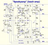
.Here is the Spooky 1.2 schematic. I have made this and found it excellent (though I've not made any of the others for comparison).
Attachments
Hi Thimios,
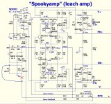
the schematic you posted is very similar to that linked in the first post of this thread (only two transitor types are different and 2 resistors).
But one thing seems to me is wrong.
The feedback basis should not be connected directly to ground, but in that way I have drawn, if R3 is the anti hum resistor. Do you agree?
Attachments
Apakah ic based v 1.1 bisa dirubah untuk clas h ?(below 1/2) update in schema with a few tips.
With most "cheap" dual OP-amps, 180R -220R is needed for
R6/R7. The current of Vcc/Vee varies between devices.
The ratio of R8/R9 will increase the transconductance of the IC.
The worst (5532) , needs 2X - R8=R9 to give the (below2) 50+db CLG.
Below this gain , thd20 suffers. Bode plot is a typical CFA result , 10K
at the "break-point".
Of the 10+ IC models I have tried , none have oscillated ... some have
given more CLG (almost 60db) . UG has varied from 600K to 1.2mhz.
No PCB yet , before I perfect the circuit. (run more sims)
OS
I can only confirm that this 560R is connected to <<dirty>> gnd, not at the lifted.Hi Thimios,
the schematic you posted is very similar to that linked in the first post of this thread (only two transitor types are different and 2 resistors).
But one thing seems to me is wrong.
The feedback basis should not be connected directly to ground, but in that way I have drawn, if R3 is the anti hum resistor. Do you agree?
HI,
this is the last version ?
I will have a lot of capacitor in my amp and I would like to limit the current as much time as possible
thanks
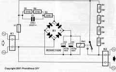
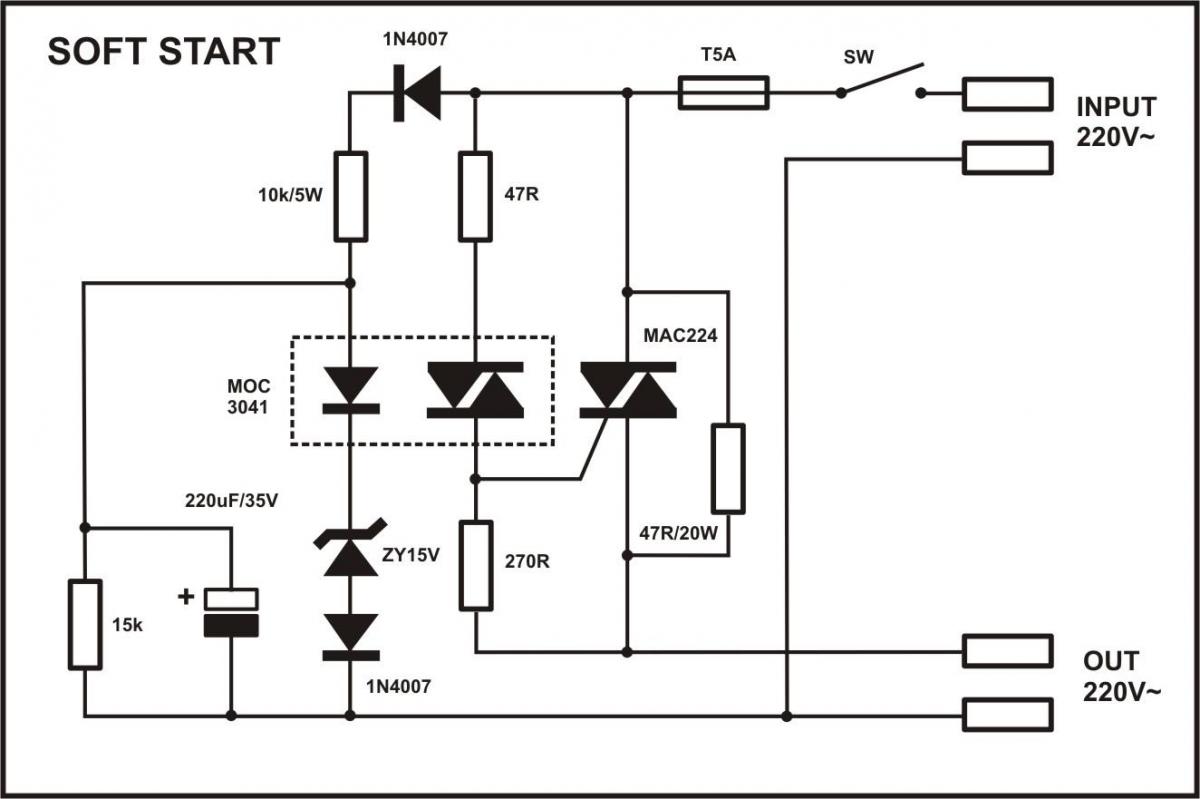
Hallo Ultimate,
I have build that circuit and it works, but I prefer this circuit with the relay bypassing the softstart part.
This is a good solution, the only idea comes into my mind, to replace R4-R7 with NTC, such SL22-10008, to avoid fire, if the relay, or relay driver circuit fails.
Sajti
This is a good solution, the only idea comes into my mind, to replace R4-R7 with NTC, such SL22-10008, to avoid fire, if the relay, or relay driver circuit fails.
Sajti
Yes, that's many commercial products have been using, space saving too
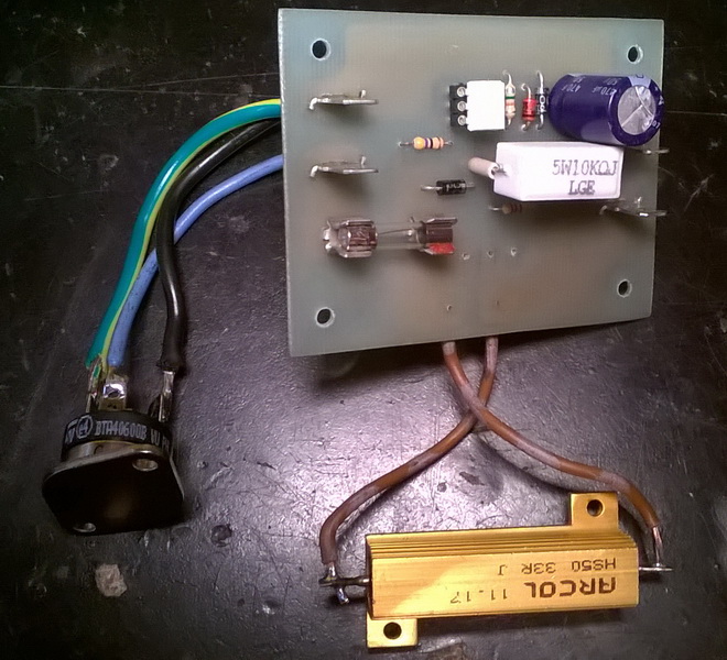
I have made a few of these and they work. You can also buy them on eBay cheap.
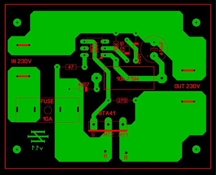
I added a 24V Zener across the coil to protect it and to suppress transients.
R1 and R2 should be 1W or more. Especially if your mains voltage is 240V.
Some 1/4W and 1/2W resistors have a low working voltage spec. That is why these two resistors are in series.
I also used two NTC's in series instead of R4 to R7.
The circuit is at mains voltage so don't touch it.
Hope that helps.
- Home
- Amplifiers
- Solid State
- Slewmaster - CFA vs. VFA "Rumble"