Just checked. Yes. Continuity exists.
Really
")
If there is continuity (it has to be a short... as in a piece of wire short) then both pins would have the same voltage but they haven't. One opamp has the correct +15v and the other an incorrect -15v
Its very difficult without actually being there and seeing what you are doing and what ranges you are using on the meter
Voltage readings are pretty conclusive. If you measure the voltage between the two pin 8's then you would see around 30 volts (or -30 depending on meter lead polarity). That's proof there is no continuity.
@Mooly
You are probably correct about 4558, missing corect voltage on pin 8, but you were on wrong path with thinking that something is wrong with semiconductors and resistors in the amp section. Please don't be missunderstood, I understood your point of view.
I hope that SONDEKNZ will solve his problem by correcting supply issue on 4558 of the right channel.
It is not unreal that opamp will fail, despite it's overcurrent protection.
Also, on pin 2 it is strange voltage, it should be voltage of the amp output (in this amp fault condition), it monitors DC offset.
Probably crack on the board, or cold joint.
One area that's confusing when describing things is that (on the diagram I have) the opamps within each package are swapped around. Pins 1,2 and 3 in one channel and pins 5,6 and 7 in the other. Makes no difference to the operation of course.
If I'm honest I've only just noticed that. It makes no difference to the supply problem but is confusing when describing things.
we will see, if he resolder opamp and check is there good connection to the power supply.
I am little suspicious why he didn't already do that, I think he is afraid of doing so.
After his exact work we can go further.
I am not saying that I am right, but we have to eliminate possible fault and go to another presumption.
As I said this is my philosophy, somebody have other, I assumed that problem might be on the opams which regulate DC offset of the amp because there are no problems with fuses, or burnt resistors, to me that was the lead.
Last edited:
CONTINUITY & MEASUREMENTS...
MOOLY
I used the CONTINUITY setting on my multimeter to test between the 02 LEG-8s. One test-pin connected to each LEG-8. Continuity tone sounded each time. Never failed. Hard to imagine that I might have done this wrongly.
I figured that this was a correct reading because the schematic shows a clear line of connection between these two LEGS. Your comment about LEG-8s should read the same prompted me to recheck all of the LEG measurements.
So, I rechecked the LEG-8 measurements (VDC) again and you are correct. They are both around 14.84, but not stable at all. The values slowly tumble around.
(It seems I recorded the figures wrongly last time. That NEGATIVE symbol in front of the measurement was a mistake. Apologies.)
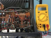
With my error in mind, I re-checked all measurements again, with the amp powered-up - se photo attached for VDC range - as follows: -
4558D OPAMP, Right (Suspect)
LEGS (VDC)
1: -13.28 (Unstable)
2: -00.43
3: -00.02 (Unstable)
4: -15.03
5: 00.00
6: -10.34 (Unstable)
7: -7.49 (Unstable)
8: 14.84 (Unstable)
4558D OPAMP, Left
LEGS (VDC)
1: -00.91
2: 00.00
3: 00.00
4: -15.03 (Unstable)
5: 00.10
6: 00.10
7: 00.87 (Unstable)
8: 14.84 (Unstable)
MOOLY
I used the CONTINUITY setting on my multimeter to test between the 02 LEG-8s. One test-pin connected to each LEG-8. Continuity tone sounded each time. Never failed. Hard to imagine that I might have done this wrongly.
I figured that this was a correct reading because the schematic shows a clear line of connection between these two LEGS. Your comment about LEG-8s should read the same prompted me to recheck all of the LEG measurements.
So, I rechecked the LEG-8 measurements (VDC) again and you are correct. They are both around 14.84, but not stable at all. The values slowly tumble around.
(It seems I recorded the figures wrongly last time. That NEGATIVE symbol in front of the measurement was a mistake. Apologies.)
With my error in mind, I re-checked all measurements again, with the amp powered-up - se photo attached for VDC range - as follows: -
4558D OPAMP, Right (Suspect)
LEGS (VDC)
1: -13.28 (Unstable)
2: -00.43
3: -00.02 (Unstable)
4: -15.03
5: 00.00
6: -10.34 (Unstable)
7: -7.49 (Unstable)
8: 14.84 (Unstable)
4558D OPAMP, Left
LEGS (VDC)
1: -00.91
2: 00.00
3: 00.00
4: -15.03 (Unstable)
5: 00.10
6: 00.10
7: 00.87 (Unstable)
8: 14.84 (Unstable)
Attachments
JUMPING IN!
PITBUL
I'm not afraid to tackle the resoldering of the OPAMP LEGS. I just can't see a quality way of doing it from above the circuit board. So this means pulling the board out.
I'm just worried that pulling out the entire power supply board might disturb other nearly 40-year old components and wiring, and cause more faults.
This is why I am exhausting all options before leaping in.
Actually, I'm looking forward to getting underneath the board and having a good look around. I'm hoping that it will help me better understand the schematic.
Anyways, it seems that the time has come to leap-in, so it is my plan to get the board out this weekend.
Exciting!
MEASURING U1 and U2; D1 and D2...
DRUIDAUDIO
Thanks for this suggestion.
Measurements (VDC) between Chassis Ground and these test points are as follows: -
U1: 1.63
U2: 7.8
D1: -1.56
D2: 5.52
Way off where they need to be, I'm sure.
I do hope these readings reveal something helpful...
DRUIDAUDIO
Thanks for this suggestion.
Measurements (VDC) between Chassis Ground and these test points are as follows: -
U1: 1.63
U2: 7.8
D1: -1.56
D2: 5.52
Way off where they need to be, I'm sure.
I do hope these readings reveal something helpful...
Last edited:
PART REPLACEMENT: 4558D JRC 2212???
Guys
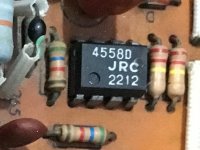
I have cast around looking for replacement parts for my suspect 4558D JRC 2212 OPAMP. (See photo...)
The nearest similar part that I could find on offer (globally) is called 4558D JRC 6044B - so perhaps not identical. Would this part work as a drop-in replacement for my suspect OPAMP? (See attached Datasheet...) If so, these would have to be shipped from the US so up to a 1-month wait here in NZ...
Alternatively, a local supplier has a supply of 4558D JRC 0079T that I could get my hands-on in a week's time. Would this part work as a drop-in replacement for my suspect OPAMP?
Alternatively, another local supplier provides a "generic" range of 8-leg OPAMPS that appear to be similar. They are called the NATIONAL SEMICONDUCTOR LM741 "family" and have a few variations including LM741, LM741A and LM741C. The variations within the family appear to relate to just SUPPLY VOLTAGE and OPERATIONAL TEMPERATURE RANGE specs. (See datasheet attached) Would this part work as a drop-in replacement for my suspect OPAMP? If these could work fine, I could grab a couple of these parts today, for a weekend swap-out project!
Can I be guided by you guys on this one please? Appreciated.
Guys
I have cast around looking for replacement parts for my suspect 4558D JRC 2212 OPAMP. (See photo...)
The nearest similar part that I could find on offer (globally) is called 4558D JRC 6044B - so perhaps not identical. Would this part work as a drop-in replacement for my suspect OPAMP? (See attached Datasheet...) If so, these would have to be shipped from the US so up to a 1-month wait here in NZ...
Alternatively, a local supplier has a supply of 4558D JRC 0079T that I could get my hands-on in a week's time. Would this part work as a drop-in replacement for my suspect OPAMP?
Alternatively, another local supplier provides a "generic" range of 8-leg OPAMPS that appear to be similar. They are called the NATIONAL SEMICONDUCTOR LM741 "family" and have a few variations including LM741, LM741A and LM741C. The variations within the family appear to relate to just SUPPLY VOLTAGE and OPERATIONAL TEMPERATURE RANGE specs. (See datasheet attached) Would this part work as a drop-in replacement for my suspect OPAMP? If these could work fine, I could grab a couple of these parts today, for a weekend swap-out project!
Can I be guided by you guys on this one please? Appreciated.
Attachments
Last edited:
4558D JRC 0079T will do the job just fine.
But LM741 is a single opamp, so it is not your replacement, 4558 is a dual opamp.
I understand that you are worried about wiring, but that is part of the job, be gentle and you'll have everything in order when you turn around board.
I don't understand what is your place, because parts you mentioned are from mid 80's of the previous century. Also, who suggested LM741 is not expert in electronics, so beware of his opinion.
If you have unstable power supply of the opamp (pins 4 & 8), you have clear sign of poor filtering, or another language speaking your capacitors are probably bad.
02 x 4558D JRC 0079T (Ordered and on their way!)
Many thanks for the confirmation, PITBUL.
As per your recommendation, I've ordered the 4558D JRC 0079T OPAMPS. Pretty cheap locally, so I thought I'd grab two.
Not quite sure what you are asking here, but yes, the amp is nearly 40-years old (Circa 1981 build) so I was a bit worried parts might be too hard to find. I feel lucky that I've been able to grab these two OPAMPS locally.
You have commented that it is the poor filtering - due to aging capacitors - that may have caused the OPAMP problems. So recapping is well overdue. Any new Electrolytic Capacitors and Resistors will also be easy to get locally.
Now that I know the parts are only a few days away, tomorrow morning, I will start removing the Power Supply Board.
I will be very gentle with this old girl... Looking forward to it!
I will try to document the process by photo - here.
Many thanks for the confirmation, PITBUL.
As per your recommendation, I've ordered the 4558D JRC 0079T OPAMPS. Pretty cheap locally, so I thought I'd grab two.
I don't understand what is your place, because parts you mentioned are from mid 80's of the previous century.
Not quite sure what you are asking here, but yes, the amp is nearly 40-years old (Circa 1981 build) so I was a bit worried parts might be too hard to find. I feel lucky that I've been able to grab these two OPAMPS locally.
You have commented that it is the poor filtering - due to aging capacitors - that may have caused the OPAMP problems. So recapping is well overdue. Any new Electrolytic Capacitors and Resistors will also be easy to get locally.
Now that I know the parts are only a few days away, tomorrow morning, I will start removing the Power Supply Board.
I will be very gentle with this old girl... Looking forward to it!
I will try to document the process by photo - here.
You can probably see how the devil is in the detail with all this
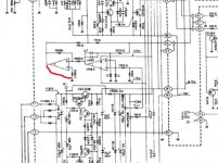
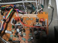
I would remove the opamp from the equation and this can be done in a couple of minutes. Just locate the resistors that connect to the opamp as shown here and link those two points together. You can do that on the top of the board in seconds. Use your meter to locate which end of the resistor goes to the appropriate pin/s.
See if doing that brings the main amp out of protection.
Changing parts on spec can lead to disaster because of the possibility of introducing new issues. Fix the fault first, then think about what else needs to be looked at... that would be my advice anyway.
Attachments
Bypassing OPAMP to test Power-up?
MOOLY
I'm very happy to try this.
Earlier in this thread you suggested bypassing the OPAMP simply by earthing LEG-7 to Chassis Ground. I never tried it.
Will this achieve the same thing? This would be easier to achieve for me.
It's just that I have been poking and prodding for quite a while, with my multimeter pin set in continuity mode. One LEG-5 and the other trying to find a resistor that is connected. No luck at all so far.
Will Chassis Grounding LEG-7 achieve the same thing?
BYPASSING OPAMP (Short across LEG-5 and Associated Resistor)
MOOLY
I managed to find the resistor associated with LEG-5, using the CONTINUITY mode, as you described.
I attached a thin (white) wire to LEG-5 and to the other end of the Resistor knowing that this would leave the Resistor involved, as you prescribed.
(See Photo...)
I tried to power-up but the Protection Circuit still locked me out. No progress there.
I'm not sure what I have just proven, if anything...
Attachments
Does pin 7 of the opamp now read dead short to ground (with the amp off)? That is what we want.
Pin 5 doesn't go to ground directly, its the other end of the resistor connected to pin 5 that does.
Also measure the DC offset at the main amplifier output in this new condition.
Pin 5 doesn't go to ground directly, its the other end of the resistor connected to pin 5 that does.
Also measure the DC offset at the main amplifier output in this new condition.
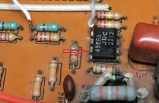
That board looks very crusty around the IC. If the amp performs OK with the shorting link then it might be worth giving the opamp and its pins a scrub with iso (alcohol), particularly on the pins 1 to 4 side. Don't be afraid of wetting the board and components with iso.
The input to the servo is high impedance and so easily affected by unwanted conductivity. The IC is still the last suspect in all this... yes it might be faulty but I certainly wouldn't bet on.
The input to the servo is high impedance and so easily affected by unwanted conductivity. The IC is still the last suspect in all this... yes it might be faulty but I certainly wouldn't bet on.
My thinking was: that opam is easily available in electronic spare parts store and to me your location written in the sign confuses me. My thoughts were that in Auckland New Zeland there must be many such stores, or there is something wrong with my perception.
If you are on some island nearby, then I absolutely understand why this opam will travel few days, that is the point.
Ok, Mooly push it, I think he is novice to schematics and electronic parts, but as I can see he is doing very well. I have so many "friends" who says that they understand electricity (or electronics), but they will never be brave to do the repairs like SONDEKNZ. If he isn't so persistant, I would pull out, now I am interested on the result.
Some more quick measurements...
MOOLY
I can see that I did attach my thin white wire to the wrong leg.
While in this condition - before I change the wire to LEG-7 - I have provided some more measurements, as you have requested.
P1 (LEFT): .1 VDC (Perfect!)
P2 (RIGHT): 6.8VDC
MOOLY
I can see that I did attach my thin white wire to the wrong leg.
While in this condition - before I change the wire to LEG-7 - I have provided some more measurements, as you have requested.
There appears to be no CONTINUITY on my multimeter between LEG-7 and Chassis Ground.Does pin 7 of the opamp now read dead short to ground (with the amp off)? That is what we want.
Yes. I understand that. That is why I connected the Resistor on the far side, so that the Resistor still stays involved in this little work-around.Pin 5 doesn't go to ground directly, its the other end of the resistor connected to pin 5 that does.
Checking DC OFFSET with the amp power ON: -Also measure the DC offset at the main amplifier output in this new condition.
P1 (LEFT): .1 VDC (Perfect!)
P2 (RIGHT): 6.8VDC
- Status
- This old topic is closed. If you want to reopen this topic, contact a moderator using the "Report Post" button.
- Home
- Amplifiers
- Solid State
- A501 / Z501 Luxkit Amplifier schematic