Insomnia...
Combining of a bit of Kiwi Ingenuity (me) and Ancient Chinese Wisdom (Rachel - not so ancient...) we managed to get the Desolder Vacuum Pump working.
Yippee Doodle!

Well I couldn't sleep... I awoke at 4am and determined to fix this sucker.
I went back through everything I had done. I sucked-out solder and flowed-in new stuff. Tested for continuity on every joint that I know should not be joining the next. Over and over again.
I could not find a short.
...I then managed to remove the (suspect) 14558D OPAMP. In went the new one - bloody easy with a soler sucker pump!!! - and I included the tiny polystyrene caps that shared some of the legs.
I decided that I had time to give the Power Supply board a bit of a wash. First I tried SCA ELECTRICAL CONTACT & PARTS CLEANER and whilst effective, it just seemed to move the gime from one place to another. Next I tried a bit of MINERAL TURPENTINE - testing first to make sure that it did not remove the circuit board typeface/values etc. The turps worked well.
I have discovered that the board is actually quite clean, but the colour around the 4 x 39K/1W Resistors is permanently darkened by over-heating. If I ever get that far, these Resistors need to double in W value - or maybe more IMHO!
I knew I didn't have a replacement fuse - the main fuse that blew previously was a 10A jobbie, but the schematic calls for a 5A and a little sticker by the fuse holder stated 6A. 10A seemed a bit high to me, but someone had stuck it in there a long time ago...
Anyways, at 5:30am there was not much chance of getting a replacement fuse, so I went for it and photographed, documented, snipped, stripped, sucked and soldered for a few hours. Finally I had replaced all of the manky-looking solder joints on the control panel switches.
I still had time, so I dressed the wiring, twisting like channels and ran Chassis Ground channels on their own.
She was looking pretty good for an old girl!
Eventually, I was able to go and purchase some fuses. I settled on a pack of 10A (Just in case), a pack of 7.5A (As close to 6 as I could buy) and a pack of 5A just in case I lost either of the two other 5A fuses in the circuit.
Once again, I gave her the once over. The twice over and then again.
With Rachel and I standing well back, with fingers crossed, I threw the switch!
(Moment of truth!)
She powered-up. Her tired red eye blinked for a while, then stabalised.
She's sitting here hot and waiting to sing...
I couldn't help feel a fool, when I had earlier realised why I had blown a fuse. The fact is that I was sooooooo focused on the amp itself, last time around I had forgotten she is a 110V Granny, retired in a 240V village. I had given her a 240V face lift!!! Little wonder that she had put her foot down.
It was my fault the fuse had blown. My bad... I guess we will never know if it was a crook solder joint or if it was the suspect OPAMP that was faulty.

From here, I'm gonna walk through the DC measurements again and see what we find.
I remain acutely aware that if I don't recap sometime soon, I could damage an OPAMP and have to start again; so a full electrolytic recap is just around the corner.
(Do you guys agree?)
Looking forward to that, anyway.
More results soon...
Combining of a bit of Kiwi Ingenuity (me) and Ancient Chinese Wisdom (Rachel - not so ancient...) we managed to get the Desolder Vacuum Pump working.
Yippee Doodle!
Well I couldn't sleep... I awoke at 4am and determined to fix this sucker.
I went back through everything I had done. I sucked-out solder and flowed-in new stuff. Tested for continuity on every joint that I know should not be joining the next. Over and over again.
I could not find a short.
...I then managed to remove the (suspect) 14558D OPAMP. In went the new one - bloody easy with a soler sucker pump!!! - and I included the tiny polystyrene caps that shared some of the legs.
I decided that I had time to give the Power Supply board a bit of a wash. First I tried SCA ELECTRICAL CONTACT & PARTS CLEANER and whilst effective, it just seemed to move the gime from one place to another. Next I tried a bit of MINERAL TURPENTINE - testing first to make sure that it did not remove the circuit board typeface/values etc. The turps worked well.
I have discovered that the board is actually quite clean, but the colour around the 4 x 39K/1W Resistors is permanently darkened by over-heating. If I ever get that far, these Resistors need to double in W value - or maybe more IMHO!
I knew I didn't have a replacement fuse - the main fuse that blew previously was a 10A jobbie, but the schematic calls for a 5A and a little sticker by the fuse holder stated 6A. 10A seemed a bit high to me, but someone had stuck it in there a long time ago...
Anyways, at 5:30am there was not much chance of getting a replacement fuse, so I went for it and photographed, documented, snipped, stripped, sucked and soldered for a few hours. Finally I had replaced all of the manky-looking solder joints on the control panel switches.
I still had time, so I dressed the wiring, twisting like channels and ran Chassis Ground channels on their own.
She was looking pretty good for an old girl!
Eventually, I was able to go and purchase some fuses. I settled on a pack of 10A (Just in case), a pack of 7.5A (As close to 6 as I could buy) and a pack of 5A just in case I lost either of the two other 5A fuses in the circuit.
Once again, I gave her the once over. The twice over and then again.
With Rachel and I standing well back, with fingers crossed, I threw the switch!
(Moment of truth!)
She powered-up. Her tired red eye blinked for a while, then stabalised.
She's sitting here hot and waiting to sing...
I couldn't help feel a fool, when I had earlier realised why I had blown a fuse. The fact is that I was sooooooo focused on the amp itself, last time around I had forgotten she is a 110V Granny, retired in a 240V village. I had given her a 240V face lift!!! Little wonder that she had put her foot down.
It was my fault the fuse had blown. My bad... I guess we will never know if it was a crook solder joint or if it was the suspect OPAMP that was faulty.
From here, I'm gonna walk through the DC measurements again and see what we find.
I remain acutely aware that if I don't recap sometime soon, I could damage an OPAMP and have to start again; so a full electrolytic recap is just around the corner.
(Do you guys agree?)
Looking forward to that, anyway.
More results soon...
Attachments

New CLASS-A DC OFFSET Readings...
Left Channel: .1V (As it should be... Perfect and Stable)
Right Channel: -.104V (Suspect...)
At least she's powering-up now. Definite progress!
😉😉😉
Left Channel: .1V (As it should be... Perfect and Stable)
Right Channel: -.104V (Suspect...)
At least she's powering-up now. Definite progress!
😉😉😉
Well it all sounds more promising 🙂
DC offsets can be of either polarity and so that in itself isn't a worry. The fact that the good channel has a similar offset value to the repaired channel suggests that all is to the original spec.
(I think I mentioned earlier somewhere that the 4558 would be a odd choice for a DC servo, at least today. A servo should really bring the offset down to a millivolt or so, however the 4558 being a normal 'transistor' type opamp and not a FET type means it can generate small DC errors related to its input bias current and these skew the overall offset. 100mv is still small and was considered acceptable many years ago)
Nice, very nice.
There is no big problem if you are testing with old caps, but for proper work it should be done.
Could you determine is there any heat on the new opamp, before you said that there is some heat around it.
You should do that by simple finger touch on top of the opamp.
After recaping you should readjust dc offset to lower value, closer to the 0,00V.
Again, I am glad that you succeed it.
You know, when I was young, some 35 years ago, my stupidity tried to switch new radio to 110V input and put it into 220V wall outlet.
After that remarkable work amplifier chip had to be replaced and I learned that I always have to check proper input voltage on multi voltage devices 🙂
So we're done???
Mooly & Pitbul
Many thanks for this feedback - and of course, the invaluable hand-holding along the way.
Appreciated.
I guess I'm thinking that there is still a problem with the amp becuase the DC OFFSET is not perfectly identical, but if DC Offset can be in either positive or negative read-outs (I'm not really sure how you can -.1V of anything LOL!) then it sounds like we might be ready to play some music.
Pitbul, it sounds like you are not too worried about the caps.
Meanwhile I'm planning a whole big Cap replacement project.
Am I wasting my time?
Bias Idle???
I was hoping you guys might be able to step me through the BIAS IDLE process.
I feel sure that it is way out as this CLASS-A Machine - with very serious self-cooling technology everywhere - never seems to get more than warm.
Trouble is, the Bias Idle Instructions require me to hook-up to a wire that is not there! (The white wire...)
I can find positions J1 and J2, but they both appear to have a naked jumper wire soldered to from the post next door:
B9 jumpers to J1;
J2 jumpers to B11
This is confusing. Also, when it comes to measuring amps, I am a little nervous.
Thoughts?
(Let me know if you need a photo of the contentious area...)
Attachments
I wouldn't adjust bias current until caps are replaced.
A class biasing can be tricky, also AB, until caps are replaced, there is possibility of unplanned current rise which will destroy your output transistors.
You can listen to some music to hear is there any non wanted distortion, or unwanted sound.
A class biasing can be tricky, also AB, until caps are replaced, there is possibility of unplanned current rise which will destroy your output transistors.
You can listen to some music to hear is there any non wanted distortion, or unwanted sound.
The circuit seems to show a different idea but there are different ways to do this.
This shows two resistors that can be fitted in place of the link. The low value part will allow you to determine the current for Class A position and the high value part for Class AB. All you are doing is measuring volt drop across a known resistor and calculating the current from that. An accurate DVM with a decent millivolt range could use the low value part for both adjustments.
You can also simply measure the voltage across the two emitter resistors related to either the upper NPN or lower PNP outputs and calculate the current in each. Add them together to get the total. No soldering or anything involved in that.
It looks like you set the AB current first, then the A due to the presets being switched in parallel with each other.
Attachments
Bias Idle
I will be sure to give the old girl a listen over the next day or so too...
Could I get you to dumb-down this paragraph a bit, for this newbie please?
I'm not sure which are the "Emitter Resistors?" If you can use the numbered positions on the schematic, I can probably locate them.
Also, I don't know about "...upper NPN or lower PNP outputs...".
Sorry MOOLY, but I'm struggling to keep up with you on this one...

Thanks PITBUL. As you've suggested, I won't crank up the bias until I've replaced the caps; but I would like to learn how to do it.I wouldn't adjust bias current until caps are replaced.
A class biasing can be tricky, also AB, until caps are replaced, there is possibility of unplanned current rise which will destroy your output transistors.
You can listen to some music to hear is there any non wanted distortion, or unwanted sound.
I will be sure to give the old girl a listen over the next day or so too...
Thanks for these thoughts MOOLY. If it is possible to find a way, I'd much prefer to measure Voltage than Current in order to play around with the Bias Idle settings.You can also simply measure the voltage across the two emitter resistors related to either the upper NPN or lower PNP outputs and calculate the current in each. Add them together to get the total. No soldering or anything involved in that.
Could I get you to dumb-down this paragraph a bit, for this newbie please?
I'm not sure which are the "Emitter Resistors?" If you can use the numbered positions on the schematic, I can probably locate them.
Also, I don't know about "...upper NPN or lower PNP outputs...".
Sorry MOOLY, but I'm struggling to keep up with you on this one...
Replacing Electrolytic Capacitors...
Apart from the massive input capacitors next to the Power Transformer, there are 14 other Electrolytic Capacitors (El. Caps) in this amp - and all appear to be located in the Power Supply area of this amp.
(Please correct me if I am wrong about this...)
Having done quite a bit of research on this topic, I am keen to invest in LOW ESR capacitors in the Power Supply.
It seems that in the (nearly) 4 decades since this amp was built, capacitors have come a long, long way.
It's now possible to get polyester and polypropylene caps in 10uF / 250V values and featuring lower ESR ratings than El. Caps; and better temperature handling performance that El. Caps.
QUESTION: Aside from any prohibitive pricing, is there any reason at all, why I should not replace all or some of the Power Supply El. Caps with some of the new alternatives - where physical dimensions suit the circuit board?
(See pic below for one possible alternative...)
Attachments

To low an esr can cause some, mostly low dropout voltage types so not this one, regulators to oscillate...
the size of these can be a pain to fit..
the size of these can be a pain to fit..
The at AU$1 each at radio spares 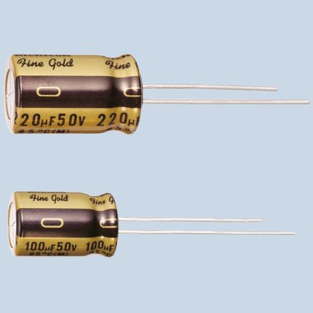
get good reviews and being a bit bigger than most others might be easier to fit
The one i highlighted in the attachment being in the feedback loop and marked bp for Bipolar so.. maybe
100uf-nichicon muse

diyaudio.com nichicon-muse-es-bipolar-caps-measured-120db-thd-140db-imd
regards
james
get good reviews and being a bit bigger than most others might be easier to fit
The one i highlighted in the attachment being in the feedback loop and marked bp for Bipolar so.. maybe
100uf-nichicon muse
diyaudio.com nichicon-muse-es-bipolar-caps-measured-120db-thd-140db-imd
regards
james
Attachments
@tvi
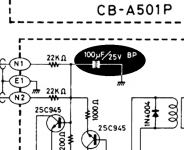
please don't confuse SONDEKNZ with that bipolar capacitor (100uF/25V), it is not feedback capacitor, it is intended for protection circuit (to detect high dc offset).
This amplifier was designed with minimum electrolytics, or in other words only electrolytics are in power supply board, so there are no ageing parts in the signal path or in the supply rails on power amp board.
Nice choice for capacitors, I recomend them, SONDEKNZ you can buy them, there are intended for audio equipment.
A Couple of Votes to Stay with Electrolytics...
TVI: Thanks for the recommendations and links to other discussions.
PITBUL: Are you also recommending the NICHICON MUSE?
Still, I would like for someone to answer my question about alternatives, as there does not seem to be any good reason to stay with El. Caps - unless of course, they are the very best type of capacitor for the job.
Meanwhile, I am looking at the 14 (BLUE) RUBYCON El Caps currently fitted and wondering: Are these caps really 40-years old? Or might somebody have previously recapped this amp - and so they don't need changing? How can I be sure?
(Close-up photo below...)
Attachments

A Couple of Votes to Stay with Electrolytics...
Actually, of the 14 El. Caps, 13 are Rubycon Blue-on-Blue, but one is Rubycon Pale Grey with Black Print...
Actually, of the 14 El. Caps, 13 are Rubycon Blue-on-Blue, but one is Rubycon Pale Grey with Black Print...
Last edited:
If you look at the diagram you will see two 'dual' resistor packages marked 0.22 ohm 5 watt that connect to the output transistors.
The junction of these four 0.22 ohm resistors is the main amplifier output.
You measure the bias current by measuring the voltage across either set of resistors. It doesn't matter which. So you connect the meter negative lead to this junction point and then measure the voltage across one set of resistors.
Although the current should be equal in each, in practice it will not be due to transistor tolerances.
So for example 100 milliamp bias could measure as approximately 14 mv across one resistor and 8mv across the other meaning that one transistor is passing around 63ma and the other around 36ma. Add them together and you get the total current flow.
The blue Rubycons definitely look original to me and are typical of mid to late 1970's equipment. Personally I would replace all such caps with modern replacements, nothing exotic, just stick to top quality commercial grade parts of 105C rating.
@SONDEKNZ
Yes, I recommend nichicon MUSE, FineGold caps are also MUSE caps.
These caps are intended for audio equipment.
Cap that is different from blue ones, is probably bipolar one mentioned by tvi, it should be bipolar, marked BP (or maybe NP-non polarised), so you should use that one with marking BP from nichicon MUSE series.
Mooly described nicely how to measure bias current without puting ampere meter in the circuit. Be careful with the probes, fix them before measuring, don't shake your hands 🙂
Yea thes blue rubycon, binned heaps from old amps...
See attached
almost ala the pic in japan of A501 have the same caps
They are even in the M120A which is basically the same amp
See attached
almost ala the pic in japan of A501 have the same caps
They are even in the M120A which is basically the same amp
Attachments
Last edited:
- Home
- Amplifiers
- Solid State
- A501 / Z501 Luxkit Amplifier schematic