Parts Availability in NZ...
PITBUL
In reply to your questions...
I'm sure you are probably right. NZ is a modern place and we are based here right in the middle of Auckland City. I guess that the issue is: Because I am so new to this stuff, I have been looking for an IDENTICAL PART / SAME BRAND / SAME MODEL to replace. As you are more experienced in these matters, you probably know that there are hundreds of alternative SIMILAR PARTS that would still do the job. The challenge is, that I don't possess your knowledge or understanding. The good news is that I have secured some parts that you have confirmed will do the job - and they are brand new!
In terms of my credentials: I have had no electronics training at all. But Audio and HiFi is my passion, so over the years I have been trying to teach myself electronics. I have built a kitset tube preamp and spent 13 years modifying it to sound better and better. (Eventually, a stranger visited and loved the sound of my preamp so much, he paid me thousands for it and took it away... LOL!) I also restore HiFi loudspeakers and improve crossovers, etc. They always come out looking and sounding WAY better!
I certainly don't claim to be anything more than a novice in all this, but I do believe that I am teachable; and that if someone else can figure it out - given the right information - so can I.
(Let's see if I'm right about that last bit... 😀 )
Thanks for hanging in here with me on this project, PITBUL. (And MOOLY!)
PITBUL
In reply to your questions...
My thinking was: that opam is easily available in electronic spare parts store and to me your location written in the sign confuses me. My thoughts were that in Auckland New Zealand there must be many such stores; or there is something wrong with my perception.
I'm sure you are probably right. NZ is a modern place and we are based here right in the middle of Auckland City. I guess that the issue is: Because I am so new to this stuff, I have been looking for an IDENTICAL PART / SAME BRAND / SAME MODEL to replace. As you are more experienced in these matters, you probably know that there are hundreds of alternative SIMILAR PARTS that would still do the job. The challenge is, that I don't possess your knowledge or understanding. The good news is that I have secured some parts that you have confirmed will do the job - and they are brand new!
In terms of my credentials: I have had no electronics training at all. But Audio and HiFi is my passion, so over the years I have been trying to teach myself electronics. I have built a kitset tube preamp and spent 13 years modifying it to sound better and better. (Eventually, a stranger visited and loved the sound of my preamp so much, he paid me thousands for it and took it away... LOL!) I also restore HiFi loudspeakers and improve crossovers, etc. They always come out looking and sounding WAY better!
I certainly don't claim to be anything more than a novice in all this, but I do believe that I am teachable; and that if someone else can figure it out - given the right information - so can I.
(Let's see if I'm right about that last bit... 😀 )
Thanks for hanging in here with me on this project, PITBUL. (And MOOLY!)
In the interim...
While I am waiting for the massive Power Supply Capacitors to *discharge - before I try swapping wires around - I thought I would mention...
This old 1981 LUXMAN LUXKIT AVANCE Z501 normally sounds so darned good, I just can't abandon it!
It is in my thinking that sooner or later - depending upon family demands at my end - I will transplant this amp into a modern enclosure. This will give me the chance to really "go to town" on this amp and give it a real Birthday, with all the trimmings.
I guess a purist would want to keep it all stock in the current (plywood) enclosure, but frankly, it's not much more than an old crate.
The one thing that I would like to change about the circuit, is the two GAIN potentiometers. I find that a real hassle, when using this amp without a preamp. So, I would be keen to amalgamate this into a single STEREO pot. Something like an ALPS BLUE would do the job I reckon.
*If someone has a neat trick to speed-up the discharge of these Capacitors, I'd love to hear about it!!!
Attachments
Back to the test...
MOOLY
I swapped my thin white jumper wire to LEG-7 - as you originally suggested - but this time I was unable to secure it, as it is so darned close to the LEG-8 you mentioned. So I held it there manually.
I believe that this achieved the little workaround, exactly as you had drawn earlier in this thread.
This time, there was a different result.
Previously, the amp Protection Circuitry locked the amp up, leaving the red LED winking in disapproval.
This time, I heard a relay "click" and the red LED was left solid red.
This definitely seems like progress!
I know it would have been helpful to re-measure P1 and P2 at that point, but holding the white jumper manually, it was just not possible. Sorry.
Now here is a question: I cannot clearly recall whether this LED's normal "PLAY" position is solid red, or whether it should change to solid green. I just can't recall.
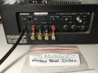
@DRUIDAUDIO Can you confirm what the normal "PLAY" state of the Control Console LED is on your Z501 please? Is it solid red? Or does it turn solid green?
In any event, I'm not sure what I have just proven - if anything - but hopefully this is good news!
MOOLY
I swapped my thin white jumper wire to LEG-7 - as you originally suggested - but this time I was unable to secure it, as it is so darned close to the LEG-8 you mentioned. So I held it there manually.
I believe that this achieved the little workaround, exactly as you had drawn earlier in this thread.
This time, there was a different result.
Previously, the amp Protection Circuitry locked the amp up, leaving the red LED winking in disapproval.
This time, I heard a relay "click" and the red LED was left solid red.
This definitely seems like progress!
I know it would have been helpful to re-measure P1 and P2 at that point, but holding the white jumper manually, it was just not possible. Sorry.
Now here is a question: I cannot clearly recall whether this LED's normal "PLAY" position is solid red, or whether it should change to solid green. I just can't recall.
@DRUIDAUDIO Can you confirm what the normal "PLAY" state of the Control Console LED is on your Z501 please? Is it solid red? Or does it turn solid green?
In any event, I'm not sure what I have just proven - if anything - but hopefully this is good news!
@druidaudio
@druidaudio
Can you confirm what the normal "PLAY" state of the Control Console LED is on your Z501 please? Is it solid red? Or does it turn solid green?
@druidaudio
Can you confirm what the normal "PLAY" state of the Control Console LED is on your Z501 please? Is it solid red? Or does it turn solid green?
Knee Deep in the Hoopla!
Well, I had talked about it for long enough... The time came to leap in!
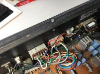
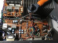
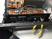
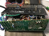
The next few posts will document the next part of my journey - which required gaining working access to the underside of the Power Supply circuit board.
A picture paints a thousand words, so I will let the photos tell the story...
Well, I had talked about it for long enough... The time came to leap in!
The next few posts will document the next part of my journey - which required gaining working access to the underside of the Power Supply circuit board.
A picture paints a thousand words, so I will let the photos tell the story...
Attachments
-
 POWER SUPPLY BOARD REMOVAL 1.jpg733.1 KB · Views: 186
 -
 POWER SUPPLY BOARD REMOVAL 2.jpg668.9 KB · Views: 175
 -
 POWER SUPPLY BOARD REMOVAL 3.jpg953.6 KB · Views: 180
 -
 POWER SUPPLY BOARD REMOVAL 4.jpg756.9 KB · Views: 96
 -
 POWER SUPPLY BOARD REMOVAL 5.jpg731.9 KB · Views: 104
 -
 POWER SUPPLY BOARD REMOVAL 6.jpg817 KB · Views: 109
 -
 POWER SUPPLY BOARD REMOVAL 7.jpg654.3 KB · Views: 103
First Glimpses!!!
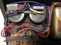
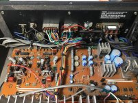
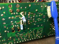
After about 30-minutes of careful and gentle persuasion, the shiny green underside of the circuit board finally emerges to reveal its secrets...
Initial observations reveal that: -
* The area of the circuit board that has been supporting the OPAMPS has been getting pretty hot; and
* On at least one prior occasion, someone else has been stirring this porridge!
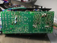
I elected to give the areas of concern a bit of a clean to see what is really happening on the underside.
I was quite surprised that many of the underside solder joints spilled into each other. Based upon several areas of judicious "scraping" that I can see, it appears that an earlier explorer has also attempted to remedy this solder spillage.
After about 30-minutes of careful and gentle persuasion, the shiny green underside of the circuit board finally emerges to reveal its secrets...
Initial observations reveal that: -
* The area of the circuit board that has been supporting the OPAMPS has been getting pretty hot; and
* On at least one prior occasion, someone else has been stirring this porridge!
I elected to give the areas of concern a bit of a clean to see what is really happening on the underside.
I was quite surprised that many of the underside solder joints spilled into each other. Based upon several areas of judicious "scraping" that I can see, it appears that an earlier explorer has also attempted to remedy this solder spillage.
Attachments
-
 POWER SUPPLY BOARD REMOVAL 8.jpg766.9 KB · Views: 119
 -
 POWER SUPPLY BOARD REMOVAL 9.jpg781.8 KB · Views: 116
 -
 POWER SUPPLY BOARD REMOVAL 10.jpg839.2 KB · Views: 109
 -
 POWER SUPPLY BOARD REMOVAL 11.jpg934.4 KB · Views: 114
 -
 POWER SUPPLY BOARD REMOVAL 12.jpg758 KB · Views: 106
 -
 POWER SUPPLY BOARD REMOVAL 13.jpg679 KB · Views: 99
 -
 POWER SUPPLY BOARD REMOVAL 14.jpg735.5 KB · Views: 110
4558D OPAMP - Close-up Photo (Circuit Rear!)
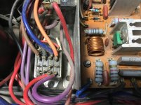
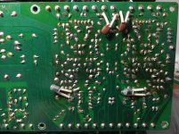
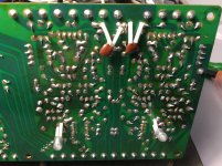
So here's a close-up photo of the contentious are.
You can make out the 8-LEGS of the OPAMP here, with a silver can (Capacitor perhaps?) entitled 471J (I think?) inserted across a couple of the legs: Legs 1 and 3 I think, but I'm not sure.
Because I can't immediately spot any obvious circuit board cracks or rubbish solder joints, I'm gonna stop right here and wait for some expert suggestions about what's next.
Attachments
Could these be COLD SOLDER JOINTS???
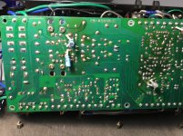
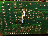
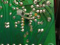
I've been staring at this circuit board all afternoon "...looking for clues" as the late Robert Palmer once famously sang.
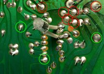
I have noticed that a number of solder joints on this board look a bit dodgy. It's almost as if the solder and the component have not quite got hot enough to become one, so there's a faint telltale "ring" around the component tail.
(I have circled these in RED for warning!)
This, compared with what I would consider to be superb solder joints, where the entire joint appears to be one piece of flawless metal, that encapsulates the component tail without any division marks.
(I have circled these with GREEN for good!)
Could the joints circled in red be potential COLD SOLDER JOINTS?
Could this be the source of my problems here?
(Interestingly, there are very few of these around the operationally normal LEFT CHANNEL, on this board...)
I've been staring at this circuit board all afternoon "...looking for clues" as the late Robert Palmer once famously sang.
I have noticed that a number of solder joints on this board look a bit dodgy. It's almost as if the solder and the component have not quite got hot enough to become one, so there's a faint telltale "ring" around the component tail.
(I have circled these in RED for warning!)
This, compared with what I would consider to be superb solder joints, where the entire joint appears to be one piece of flawless metal, that encapsulates the component tail without any division marks.
(I have circled these with GREEN for good!)
Could the joints circled in red be potential COLD SOLDER JOINTS?
Could this be the source of my problems here?
(Interestingly, there are very few of these around the operationally normal LEFT CHANNEL, on this board...)
Attachments
Yes, that are cold solder joints, to do it right you should suck (with the soldering pump) the old soldering and apply new that spot.
That is the primary reason why I was forcing you to do job with the soldering iron. For that old amp it is always good to see what is going on with solder joints.
Could you determine which opamp area is pretty hot. My suggestion is that you pull out right opamp ic and measure the voltage on the diodes which protects the input of the opamp (I am writing this way because on schematics opamps inside ic are swaped for each channel, so I can't conclude which numbers are right). Maybe you will have different DC offset on the amp output, to measure it right, do it on the resistor side which is connected to the amp out (that is correct info, diodes will limit the voltage to max 0,6-0,8V as I said).
It seems to me that opamp will do DC offset correct if it is working.
What Mooly suggested maybe will result to eliminate DC offset, but also maybe not. To correct the offset caused by some non balance in the circuit, which may be obvious after so many years, opamp will do.
Opamp is not intented to do the job if there are some sirious failure, or if there is DC offset outside the range which opamp can't manage. So, if there are the last described case, problem lies somewhere in the circuit.
First, do the cold joints, after that switch on amp and do measurement to see what hepened.
Next steps...
Thanks for the support, PITBUL.
Okay. These are cold joints. Aha! I'm not going to pretend that they will be my sole source of problems, as these cold joints have probably existed since the amp was built in 1981. However, I can imagine that over time, they slowly but surely introduce more anomalies into the circuit until one day, things just don't work right.
As you suggest, I will wait for my new desolder pump to arrive and will remedy these joints properly. The temptation - while I wait for the new machine to arrive from Australia - is to start collecting new Capacitors and Resistors for the joints that are affected. Hmmmm....?
If you don't mind, I may revisit this with you when the time comes as I'm not 100% clear on the process.
I think for now, Step 1 is - as you prescribe - to rid the board of Cold Solder Joints and then power-up and measure.
Thanks for the support, PITBUL.
Yes, that are cold solder joints, to do it right you should suck (with the soldering pump) the old soldering and apply new that spot.
That is the primary reason why I was forcing you to do job with the soldering iron. For that old amp it is always good to see what is going on with solder joints.
Okay. These are cold joints. Aha! I'm not going to pretend that they will be my sole source of problems, as these cold joints have probably existed since the amp was built in 1981. However, I can imagine that over time, they slowly but surely introduce more anomalies into the circuit until one day, things just don't work right.
As you suggest, I will wait for my new desolder pump to arrive and will remedy these joints properly. The temptation - while I wait for the new machine to arrive from Australia - is to start collecting new Capacitors and Resistors for the joints that are affected. Hmmmm....?
Could you determine which opamp area is pretty hot. My suggestion is that you pull out right opamp ic and measure the voltage on the diodes which protects the input of the opamp (I am writing this way because on schematics opamps inside ic are swapped for each channel, so I can't conclude which numbers are right). Maybe you will have different DC offset on the amp output, to measure it right, do it on the resistor side which is connected to the amp out (that is correct info, diodes will limit the voltage to max 0,6-0,8V as I said).
If you don't mind, I may revisit this with you when the time comes as I'm not 100% clear on the process.
I think for now, Step 1 is - as you prescribe - to rid the board of Cold Solder Joints and then power-up and measure.
Working through the posts...
The only result that mattered was the behaviour of the amp with pin 7 grounded. It seems like doing this did indeed change the behaviour (which is good) but what we really needed was the voltage check of offset.
You could do that by anticipating that the click was the speaker relay connecting correctly and so wiring the meter across the speaker sockets and seeing what happened.
This result is a big step forward though and hopefully shows the main amp is basically OK. The circuit also seems to show a single LED, not a bi-colour type.
---------------------------------
Discharging caps. Normally the circuit itself will do that. Just check to make sure there is no high voltage across them. Anything under a couple of volts is OK to begin working on the amp. To manually discharge a large cap use a resistor appropriate to the voltage. A 4k7 2watt carbon type should cover most situations on solid state stuff.
-----------------------------------
The shiny green is a mask which we call solder resist. The board still looks like a phenolic resin type to me and will have a distinct smell as you solder on it. The discolouration in response to long term heat is perfectly normal though.
The soldering looks pretty much par for the course tbh. Look at the last pictures in post #1 here which show the kind of thing to be aware of. Some of those joints on your board look very suspect but I would beware at this stage of doing more remedial work... try and diagnose and fix the issue at hand first.
Sony CDP790 and KSS240 Restoration Project
-----------------------------
The cap marked 471 is a 470pF polystyrene type. Its 4 and 7 and then 1 zero as the multiplier. 473 would be 47,000pF or 47nF (nano) or 0.047uF.
------------------------------
So where next 🙂
Well I guess you have to replace that opamp and also clean the top area of the board around the opamp gently. The voltage you measured on pin 7 earlier is the one thing I have doubts over... because I would have expected it to be stuck more toward the supply rail than an indeterminate voltage.
That doesn't change anything as far as we are concerned, its just a case of,
1/ Is the opamp alone genuinely faulty? It would still be last on my list of suspects tbh.
2/ Is the problem contamination on the top of the board affecting the high impedance circuity of the opamp? This means replacing the opamp may well fix the issue as contamination is automatically burned off and removed.
3/ Is the problem one of the passive parts around the opamp. It happens, however unlikely.
@druidaudio
Can you confirm what the normal "PLAY" state of the Control Console LED is on your Z501 please? Is it solid red? Or does it turn solid green?
I no longer have my Z501, so cannot check and don't remember, but the manual says it should go from blinking red to continuous, so I assume this is also red?
Sorry I cannot be more helpful.

Seems like SOLID RED LED = "PLAY"...
Thanks DRUIDAUDIO. No drama.
By all accounts, it seems like a solid red LED = "PLAY".
I have several different amps, so I can't quite recall either.
Let's just see how it plays out...
Thanks DRUIDAUDIO. No drama.
By all accounts, it seems like a solid red LED = "PLAY".
I have several different amps, so I can't quite recall either.
Let's just see how it plays out...
4558D OPAMPS ARRIVED!!! (But...)
@Pitbul
Well, as agreed last week, I ordered the 02 x [4558D JRC 0079T0] And what arrived?
02 x [4558D JRC D001C].
(Sigh...)
Well, they certainly look the same as a 4558D JRC 2122 - as currently installed in the Z501 - but will they work the same???
Truthfully, I really have no idea.
In the event that it does not, I need to let the supplier know and seek the right OPAMPs.
(Wouldn't you think that they would run it by me first, before shipping...?)
Any light you can shed here would be appreciated.
Meanwhile, the project has stalled a bit while my new Solder-sucker machine wings it way from Australia...
(Thanks for your patience...)
4558D JRC 0079T will do the job just fine.
@Pitbul
Well, as agreed last week, I ordered the 02 x [4558D JRC 0079T0] And what arrived?
02 x [4558D JRC D001C].
(Sigh...)
Well, they certainly look the same as a 4558D JRC 2122 - as currently installed in the Z501 - but will they work the same???
Truthfully, I really have no idea.
In the event that it does not, I need to let the supplier know and seek the right OPAMPs.
(Wouldn't you think that they would run it by me first, before shipping...?)
Any light you can shed here would be appreciated.
Meanwhile, the project has stalled a bit while my new Solder-sucker machine wings it way from Australia...
(Thanks for your patience...)
@SONDEKNZ
you shouldn't worry about numbers wich follow after JRC.
Install it in the amp and finally we want to see the fault is there or not.
you shouldn't worry about numbers wich follow after JRC.
Install it in the amp and finally we want to see the fault is there or not.
Pretty much any 'unity gain stable' dual opamp would work in that position. What you ordered will be fine.
Arrival... (Solder / Desolder Tips Invited!)
My new Solder / Desolder Station has finally arrived. Very nice too. This has got to be the best Wedding Anniversary Gift ever!
(Thank you, my Rachel... )
)
So with tools and parts now in hand, this weekend promises BIG progress!
Before I start attacking this PCB - the cold solder joints and the swap-out of the suspect OPAMP - I wanted to ask a question around recommended soldering iron / desolder gun temperatures, as I don't want to do more damage than good.
My trusty old PEMCO soldering gun is 100w and just keeps getting hotter the harder I squeeze the trigger. (And you've got to love the little lightbulb at front of the gun... lol!) Trouble is, it has never provided me with any understanding as to how hot the gun actually got; nor how many watts I was triggering.
So question: What settings should these new tools be set for, for this type of close and tight PCB work?
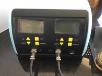
The new Soldering Iron has a maximum setting of 60W. Also, there is a temperature reading.
The new Desoldering Gun has a maximum setting of 90W. Also, there is a temperature reading.
Cheers!
My new Solder / Desolder Station has finally arrived. Very nice too. This has got to be the best Wedding Anniversary Gift ever!
(Thank you, my Rachel...
)So with tools and parts now in hand, this weekend promises BIG progress!
Before I start attacking this PCB - the cold solder joints and the swap-out of the suspect OPAMP - I wanted to ask a question around recommended soldering iron / desolder gun temperatures, as I don't want to do more damage than good.
My trusty old PEMCO soldering gun is 100w and just keeps getting hotter the harder I squeeze the trigger. (And you've got to love the little lightbulb at front of the gun... lol!) Trouble is, it has never provided me with any understanding as to how hot the gun actually got; nor how many watts I was triggering.
So question: What settings should these new tools be set for, for this type of close and tight PCB work?
The new Soldering Iron has a maximum setting of 60W. Also, there is a temperature reading.
The new Desoldering Gun has a maximum setting of 90W. Also, there is a temperature reading.
Cheers!
Attachments

Assuming you are working with normal standard cored solder (don't use lead free) then I find that a large tip and around 320C (according to my Philips iron) is about right. The tip you see in the picture below is big but would be my choice for rework. There is nothing worse than a small tip that can not hold the heat when it contacts large components.
Working with SMD. How to do it without specialised tools.
Working with SMD. How to do it without specialised tools.
Update... Beaten?
It's been ten days since my last post.
I've been wrestling with my new MICRON T2052 Soldering Desoldering Station. It arrived with next to no instructions and the Australian Agent has been less than helpful. I was wondering what I was doing wrong then realised that vital parts are actually missing, so there is no way to connect the Vacuum Hose to the main pump unit. Given that there was not even an assembly guide provded to show how the unit should be connected, it took me a while to figure this out. Anyways...
Again waiting for some response from the MICRON Agency - in the hopes that they will send me the parts they owe me; and not just ignore me - I pushed forward with just my trusty soldering iron and decided to attend to some of the cold solder joints identified earlier.
I elected to simply reheat the suspect joints and flow some new solder in too. It was a very slow process, but I did careful work and it went very well. Interestingly, these joints are so small that I needed to wear 1.5X Craft Spectacles AND use a magnifying glass to gain good visual access!!!
(I don't normally wear glasses at all!)
In all respects, I was careful to ensure that the welds did not spill-over and join others, avoiding shorts.
Once I had hit all the visually suspect looking joints, I reassembled the amp and carried out another final inspection, before hitting the power button.
(Moment of truth...!)
She powered-up and immediately blew the main protection fuse.
BUGGER!!! (As we say Down Under...)
So, I've since had time to sleep on it. I feel a bit beaten, so I've decided to put this amp project aside for a while and return to it, once my Desolder Station is fully operational.
I guess the starting point will be to re-check all the welds a be sure there are in fact no shorts - and get that right, before diving-in deeper.
This is very frustrating, as I thought I was making good progress. I'll come back to this repair project when I have more time; and a fresh and more positive attitiude.


(More later... )
)
It's been ten days since my last post.
I've been wrestling with my new MICRON T2052 Soldering Desoldering Station. It arrived with next to no instructions and the Australian Agent has been less than helpful. I was wondering what I was doing wrong then realised that vital parts are actually missing, so there is no way to connect the Vacuum Hose to the main pump unit. Given that there was not even an assembly guide provded to show how the unit should be connected, it took me a while to figure this out. Anyways...
Again waiting for some response from the MICRON Agency - in the hopes that they will send me the parts they owe me; and not just ignore me - I pushed forward with just my trusty soldering iron and decided to attend to some of the cold solder joints identified earlier.
I elected to simply reheat the suspect joints and flow some new solder in too. It was a very slow process, but I did careful work and it went very well. Interestingly, these joints are so small that I needed to wear 1.5X Craft Spectacles AND use a magnifying glass to gain good visual access!!!
(I don't normally wear glasses at all!)
In all respects, I was careful to ensure that the welds did not spill-over and join others, avoiding shorts.
Once I had hit all the visually suspect looking joints, I reassembled the amp and carried out another final inspection, before hitting the power button.
(Moment of truth...!)
She powered-up and immediately blew the main protection fuse.
BUGGER!!! (As we say Down Under...)
So, I've since had time to sleep on it. I feel a bit beaten, so I've decided to put this amp project aside for a while and return to it, once my Desolder Station is fully operational.
I guess the starting point will be to re-check all the welds a be sure there are in fact no shorts - and get that right, before diving-in deeper.
This is very frustrating, as I thought I was making good progress. I'll come back to this repair project when I have more time; and a fresh and more positive attitiude.
(More later...
)
Last edited:
- Home
- Amplifiers
- Solid State
- A501 / Z501 Luxkit Amplifier schematic