TWO DIFFERENT OPINIONS...
Thanks Mooly. So it seems that you and PITBUL differ in your assessment of the problem and the likely next step here.
No drama.
I have no idea which of you is right, but I do appreciate you offering a suggestion that will allow me to test the suspect 4558D OPAMP - in circuit - to be able to make a more informed decision and repair plan.
I just need to make sure that I correctly understand the process you have described.
Shorting 4558D leg 7 to ground is easy enough. I will be careful.
Then, if I follow you correctly, I should attempt to power-up the amp normally - leaving leg 7 shorted - which should bypass the 4558D OPAMP altogether.
Then, if this suspect OPAMP is (in fact) damaged - and the main source of the PROTECTION CIRCUIT lock-out problem - removing it will also remove the (errant) DC correction it is presently providing; and this will (perhaps) allow the amp to power up normally; if not with idyllic DC OFFSET setting.
Alternatively, if this OPAMP is working correctly - but the problem lies elsewhere in the amp - the amp will fail to power-up normally as the real source of the problem has not been eliminated and the DC at the output will still exist.
Have I got this straight? I hope so.
Can't wait to try it, but will wait for you confirmation first.
That looks a nice bit of kit 🙂 When it comes to desoldering its very much a case of what you get used to and what you are comfortable with. I like solder braid tbh and find it very quick and easy to work with.
The 4558 opamp… I would be very surprised if there were an issue there 🙂 but a simple check would just be to deliberately short pin 7 to ground. The opamp is short circuit proof and doing this would effectively remove the opamps correction voltage from the equation. The main amp should then function normally but without the active DC offset correction. In other words there would be a normal (less than 100mv say) DC offset.
Thanks Mooly. So it seems that you and PITBUL differ in your assessment of the problem and the likely next step here.
No drama.
I have no idea which of you is right, but I do appreciate you offering a suggestion that will allow me to test the suspect 4558D OPAMP - in circuit - to be able to make a more informed decision and repair plan.
I just need to make sure that I correctly understand the process you have described.
Shorting 4558D leg 7 to ground is easy enough. I will be careful.
Then, if I follow you correctly, I should attempt to power-up the amp normally - leaving leg 7 shorted - which should bypass the 4558D OPAMP altogether.
Then, if this suspect OPAMP is (in fact) damaged - and the main source of the PROTECTION CIRCUIT lock-out problem - removing it will also remove the (errant) DC correction it is presently providing; and this will (perhaps) allow the amp to power up normally; if not with idyllic DC OFFSET setting.
Alternatively, if this OPAMP is working correctly - but the problem lies elsewhere in the amp - the amp will fail to power-up normally as the real source of the problem has not been eliminated and the DC at the output will still exist.
Have I got this straight? I hope so.
Can't wait to try it, but will wait for you confirmation first.
Based on a +6 volt offset I would expect something like this:
Pin 1 = > -13v
Pin 2 = approx. +0.6v
Pin 3 = approx. 0v
Pin 4 = -15v
Pin 5 = approx. 0v
Pin 6 = approx. 0v
Pin 7 = > +13v
Pin 8 = +15v
Pin 1 = > -13v
Pin 2 = approx. +0.6v
Pin 3 = approx. 0v
Pin 4 = -15v
Pin 5 = approx. 0v
Pin 6 = approx. 0v
Pin 7 = > +13v
Pin 8 = +15v
We're all posting together 🙂
Did you see my post above yours... to first measure all voltages on the pins of the opamp?
Did you see my post above yours... to first measure all voltages on the pins of the opamp?
YUP!
I'll measure both OPAMPS. All legs - and report back shortly.
Just to be clear, we are measuring DC Voltage with one test pin grounded and the other on the leg being measured - while the amp is switched-on.
Correct?
I'll measure both OPAMPS. All legs - and report back shortly.
Just to be clear, we are measuring DC Voltage with one test pin grounded and the other on the leg being measured - while the amp is switched-on.
Correct?
Yes, black meter lead to ground and measure all the voltages with the red lead. That gives correct polarity for the readings which is all important.
4558D OPAMP - Fresh in-circuit (live) VDC measurements!
4558D OPAMP, Right (Suspect)
LEGS (VDC)
1: -13.23 (Unstable)
2: -00.43
3: -00.02
4: -15.00
5: 00.00
6: -10.36
7: -7.53
8: -14.99
4558D OPAMP, Left
LEGS (VDC)
1: -01.00
2: 00.00
3: 00.00
4: -15.10 (Unstable)
5: 00.10
6: 00.11
7: 01.00
8: 15.12
4558D OPAMP, Right (Suspect)
LEGS (VDC)
1: -13.23 (Unstable)
2: -00.43
3: -00.02
4: -15.00
5: 00.00
6: -10.36
7: -7.53
8: -14.99
4558D OPAMP, Left
LEGS (VDC)
1: -01.00
2: 00.00
3: 00.00
4: -15.10 (Unstable)
5: 00.10
6: 00.11
7: 01.00
8: 15.12
Positive rail appears missing on pin 8. It should be plus 15 volts. That suggests a problem like a crack in the print somewhere or a bad joint.
Switch the amp OFF and check for continuity between the two pin 8's of the opamps. You could link the two pins on both opamps as a test and see if the amp works normally.
I have to go out shortly, but this looks a definite easy fix based on the reading.
Switch the amp OFF and check for continuity between the two pin 8's of the opamps. You could link the two pins on both opamps as a test and see if the amp works normally.
I have to go out shortly, but this looks a definite easy fix based on the reading.
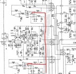
Finding a break in THAT line...
This sounds like progress MOOLY!
My challenge is relating THAT LINE to the circuit board.
I can see that it is a logical connection between the 4558D LEG-8s, but finding that physical pathway looking at the top of the circuit board is a bit daunting...
This sounds like progress MOOLY!
My challenge is relating THAT LINE to the circuit board.
I can see that it is a logical connection between the 4558D LEG-8s, but finding that physical pathway looking at the top of the circuit board is a bit daunting...
NO BREAK BETWEEN LEGS-8...
Having thought it through, given that clear continuity exists between the two LEG-8s on the different 4558D OPAMPS, I guess we cannot blame the circuit fault on a break here.
As an aside, continuity also exists between LEGS-4 on both 4558D OPAMPS, as the schematic confirms it should.
Having thought it through, given that clear continuity exists between the two LEG-8s on the different 4558D OPAMPS, I guess we cannot blame the circuit fault on a break here.
As an aside, continuity also exists between LEGS-4 on both 4558D OPAMPS, as the schematic confirms it should.
@Mooly
You are probably correct about 4558, missing corect voltage on pin 8, but you were on wrong path with thinking that something is wrong with semiconductors and resistors in the amp section. Please don't be missunderstood, I understood your point of view.
I hope that SONDEKNZ will solve his problem by correcting supply issue on 4558 of the right channel.
It is not unreal that opamp will fail, despite it's overcurrent protection.
Also, on pin 2 it is strange voltage, it should be voltage of the amp output (in this amp fault condition), it monitors DC offset.
Probably crack on the board, or cold joint.
Last edited:
COLD JOINT ON OPAMP???
PITBUL
Seems like it is worth me trying to resolder the legs on the suspect OPAMP from underneath, just in case it is (in fact) a cold solder joint... Agree?
(If this worked, it would certainly beat waiting weeks for a new one to be shipped from overseas...)
PITBUL
Seems like it is worth me trying to resolder the legs on the suspect OPAMP from underneath, just in case it is (in fact) a cold solder joint... Agree?
(If this worked, it would certainly beat waiting weeks for a new one to be shipped from overseas...)
Yes, for sure. Also check anti parallel diodes connected to this pin, they should show about 0,6 with diode check on your multimeter. Maybe they are short, if not, in this condition you should have about 0,6-0,8V on pin 2.
Parallel Diodes tested okay, I think...?
PITBUL
One side of the diodes showed continuity with Chassis Ground.
The other side of the diodes measure around .6 with no continuity.
This seems correct to my mind.
This was the same for both pairs of diodes close to each 4558D OPAMP.
(04 x diodes tested...)
PITBUL
One side of the diodes showed continuity with Chassis Ground.
The other side of the diodes measure around .6 with no continuity.
This seems correct to my mind.
This was the same for both pairs of diodes close to each 4558D OPAMP.
(04 x diodes tested...)
pull one leg of the diodes up and check, there souldn't be continuity on diodes.
It is bipolar input because you can have + or - DC offset on amp output and these diodes pull DC voltages to the +/-0,6-0,8V on the input (pin 2) of the opam.
It is bipolar input because you can have + or - DC offset on amp output and these diodes pull DC voltages to the +/-0,6-0,8V on the input (pin 2) of the opam.
Last edited:
Tricky...
That's going to require me to get the board out and access underneath.
All things considered, it seems like this is going to be my next step.
But it won't be happening tonight as it is Midnight on Thursday night, here in Auckland, NZ...
Thanks for sticking with me on this PITBUL.
(You to MOOLY)
No surprise you guys can't agree...
CANINE and BOVINE rarely see eye to eye!
(LOL!)
Hi SONDEKNZ
You can measure from ground to the following points on the output board, which are the inputs from the driver board;
U1 & U2 should be around +1V
D1 and D2 should be around -1V
If you measure anything excessive here, it is likely that you have a problem on the driver board. Go around that and check dc measurements as they are indicated on the schematic.
This way, you can at least narrow down the fault area.
Good luck!
Did you check these voltages?
- Home
- Amplifiers
- Solid State
- A501 / Z501 Luxkit Amplifier schematic