Power dissipation on that resistor is 0.5W.
With 2W resistor you are in safe margin of 3x power dissipation for dimensioning power value.
If the service manual declares power value of 1W, I would stick to that power value considering my previous statement about micro location heat area.
With 2W resistor you are in safe margin of 3x power dissipation for dimensioning power value.
If the service manual declares power value of 1W, I would stick to that power value considering my previous statement about micro location heat area.
Thanks PITBUL.
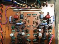
On your recommendation, I returned to the 4 x 39K Ohm / 1W Resistors in the PRE-DRIVER area. Sure enough, the sparkle returned to the sound. You were right.
See pic below of the new 1W Metal Oxide Resistors.
On your recommendation, I returned to the 4 x 39K Ohm / 1W Resistors in the PRE-DRIVER area. Sure enough, the sparkle returned to the sound. You were right.
See pic below of the new 1W Metal Oxide Resistors.
Attachments
Last edited:
On to the Power Supply / Muting Board Resistors...
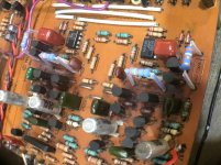
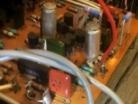
Since then, I have moved-on to the Power Supply / Muting Board, where all of the Electrolytic Capacitors are located.
While I was replacing all of the Electrolytic Capacitors, I also took the chance to change the three key resistors in that area.
All 3 Resistors were Metal Oxide types. I replaced all 3 with Wirewound types.
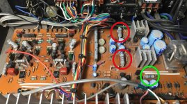
2 Resistors are 4K7 Ohms - located close to most of the Electrolytic Caps (RED circles in the pic) - and the other 1 Resistor is 47 Ohms, located near the Zenered Diodes (GREEN circle in the pic).
The specifications call for the 4K7 Ohm Resistors to be 2W; and the 47 Ohm Resistor to be 1W. I replaced all three at specified Ohm values with "lossy" 6W Wirewound Resistors, in the hopes that this would help keep noise down in this area of the circuit.
When I powered-up the amp, once again I had lost the frequency extremes.
This surprises me as the resistors that I have replaced only help with power rectification and relay control. (I think...) So, I would have thought that as long as the resistance value was correct - as specified - I would be able to install a resistor of ANY power rating, without impacting sound quality. Apparently not???
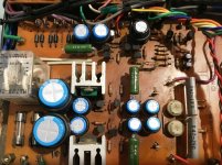
Please see the two photos attached for a "Before" and "After" view.
(NOTE: There are no heat-reliant diodes near these 3 resistors, at this end of the circuit board...)
Since then, I have moved-on to the Power Supply / Muting Board, where all of the Electrolytic Capacitors are located.
While I was replacing all of the Electrolytic Capacitors, I also took the chance to change the three key resistors in that area.
All 3 Resistors were Metal Oxide types. I replaced all 3 with Wirewound types.
2 Resistors are 4K7 Ohms - located close to most of the Electrolytic Caps (RED circles in the pic) - and the other 1 Resistor is 47 Ohms, located near the Zenered Diodes (GREEN circle in the pic).
The specifications call for the 4K7 Ohm Resistors to be 2W; and the 47 Ohm Resistor to be 1W. I replaced all three at specified Ohm values with "lossy" 6W Wirewound Resistors, in the hopes that this would help keep noise down in this area of the circuit.
When I powered-up the amp, once again I had lost the frequency extremes.
This surprises me as the resistors that I have replaced only help with power rectification and relay control. (I think...) So, I would have thought that as long as the resistance value was correct - as specified - I would be able to install a resistor of ANY power rating, without impacting sound quality. Apparently not???
Please see the two photos attached for a "Before" and "After" view.
(NOTE: There are no heat-reliant diodes near these 3 resistors, at this end of the circuit board...)
Attachments
Last edited:
SONDEKNZ
please check with the ohmmeter switches which carries signal, I think that You understand what I am talking.
Maybe they are polluted and sometimes conduct well and after some moving they do not conduct well. That could be the reason why you have sometimes good and sometimes bad sound.
please check with the ohmmeter switches which carries signal, I think that You understand what I am talking.
Maybe they are polluted and sometimes conduct well and after some moving they do not conduct well. That could be the reason why you have sometimes good and sometimes bad sound.
Switches?
Thanks PITBUL.
Because this Z501 is primarily a Power Amp, there are very few switches that carry audio signal; it only has one audio input.
One of the switches (or variable resistor, to be correct...) is (two) separate Gain Pots. But I have not messed with them at all. They remain well connected and solid. The other potential offender is the MONO/STEREO switch which has been completely resoldered by me and has provided good sound with plenty of sparkle, since been rewired.
The good sound does not come and go. The good sound left permanently, when I changed the last load of Resistors and Capacitors - on the Power Supply - Muting circuit board. The good sound has not returned since.
Tonight, I had planned to replace the new 6W resistors with the old Metal Oxide ones that came out of those same positions. They still measure up to spec.
That way I can see if indeed these resistors have any bearing on the sound.
What do you think? Good plan?
Last edited:
Good plan of course, restore to original resistors.
I would suggest that you don't change any resistors in quest of better sound with reducing dissipated heat.
If you are searching in for improving your amp, my suggestion would be to change input chinch connectors and maybe output binding post (for the last one I am not sure if you have opportunity to change them easy because of mechanical difficulties) with something better.
Improved Connectors?
PITBUL
Are you refering to the RCA Input connectors, that I should look to upgrade? I certainly will.
Also, I am looking into improving the Speaker Binding Posts, but finding very little suitable components, as this set appears to be specially prefabricated. I will probably build my own from scratch and install on a suitable "blank" piece of material.
Worth noting that I have achieved very good sound quality with all of the current connectors.
Last edited:
Yes, I am reffering to input RCA connectors (chinch is the second name which is common at my country), output binding posts are not so important as input connectors.
Input is low level and quality connector could improve sound, better connection and lower noise due better materials can be significant improvement. Output connectors already carry amplified signal which is more immune to environment noise (or call it EMC immunity).
Input is low level and quality connector could improve sound, better connection and lower noise due better materials can be significant improvement. Output connectors already carry amplified signal which is more immune to environment noise (or call it EMC immunity).

Aha!!!
After struggling to get back to the previous high levels of quality sound quality - following a recent Electrolytic Capacitor upgrade - I realised that the sound quality was mainly inferior in the LEFT CHANNEL only.
This lead to a bit of a witch hunt, during which I discovered that one of the other types of (original, unreplaced) capacitors in the Power Supply has split open.
I'm thinking that this is the cause of my sound quality my problem.
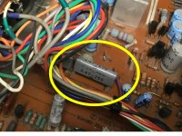
I have taken a photo (below) of the offending capacitor - shot taken before the split - in the hope that someone might be kind enough to confirm my assumptions about this part.
It's pale grey in colour, 20mm long x 10mm high x 4mm thick and appears to be a .47uF (470nF) / 250VDC Film Capacitor.
My thinking is that this could be replaced with any PET type capacitor of same values (or perhaps with higher VDC) as long as the dimensions fit.
Question: Have I got this right?
Question: Would I gain anything by moving to another type of capacitor of the same values?
Appreciate any expertise provided here.
Cheers!

After struggling to get back to the previous high levels of quality sound quality - following a recent Electrolytic Capacitor upgrade - I realised that the sound quality was mainly inferior in the LEFT CHANNEL only.
This lead to a bit of a witch hunt, during which I discovered that one of the other types of (original, unreplaced) capacitors in the Power Supply has split open.
I'm thinking that this is the cause of my sound quality my problem.
I have taken a photo (below) of the offending capacitor - shot taken before the split - in the hope that someone might be kind enough to confirm my assumptions about this part.
It's pale grey in colour, 20mm long x 10mm high x 4mm thick and appears to be a .47uF (470nF) / 250VDC Film Capacitor.
My thinking is that this could be replaced with any PET type capacitor of same values (or perhaps with higher VDC) as long as the dimensions fit.
Question: Have I got this right?
Question: Would I gain anything by moving to another type of capacitor of the same values?
Appreciate any expertise provided here.
Cheers!
Attachments
Last edited:
I see a total of six .47uf film capacitors on the schematic, two are on the output of the +/- regulated supplies and two on each channel for +/- rail decoupling. The first two I mentioned will be common to both channels so not your suspected problem. The second four I mentioned might be audible. Any .47uf film capacitor @ 100v or greater should be fine.
Craig
Craig
Botheration!
Thanks again Craig.
Upon closer inspection, the damage on this capacitor is not a split as I first thought; just a little bit of "lift" of the outer wrapper.
On second thoughts, I really don't think this capacitor is a problem at all. I will leave it as is, for the moment.
Thanks again for your expertise and support, Craig.
Back to the witch-hunt!
😱
Last edited:
Witch-hunt Ends!
I traced back all of the changes I have made, which lead me back to the two new 470pF Polystyrene Bypass Capacitors that I installed - after I accidentally melted the originals.
The one on the LEFT CHANNEL showed some very minor signs of heat distortion. Hmmmm....
Again, I replaced both with brand-new 470pF Styro Caps - but this time left around 15mm of leg to keep them well-away from the soldering heat - and this time I insulated each leg with PTFE sleeve. Mission accomplished.
I reassembled the amp, fired her up and BINGO! The old sparkle is immediately back and the old girl is sounding better than ever!!!
Actually, she seems to be improving further, as she gains burn-in time too; so I'm delighted!
This has made me realise why the original designer - named "Johnny at LUXMAN" if I am to believe what I have read - was careful to bypass the big plastic film (Polyester? PET? Not sure what...) caps, back in 1981.
This has got me wondering...
QUESTION: Do I have anything to gain by replacing these big old plastic film caps from 1981? I mean: What else am I missing?
My thinking is that surely plastic film caps have come a long way in nearly 40-years? Perhaps I should whip them out and try a modern equivalent?
What do others think?
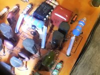
I have included snap-shots below of these big (cubic-shaped, brown-coloured) plastic caps have very few markings. All it says on one side is: -
105
T
(I assume 105 refers to maximum temperature?)
Actually, there are a couple other similar - smaller - caps on the same board. They only read: -
104
A 50
S
(Again, I assume 104 refers to maximum temperature. Not sure if the "A" is a logo or a letter...)
While I'm under the hood, are these 40-year old caps worth keeping? Or can they be easily bettered with modern equivalents?
If I should replace them, would any or the experts have any recommendations?
I traced back all of the changes I have made, which lead me back to the two new 470pF Polystyrene Bypass Capacitors that I installed - after I accidentally melted the originals.
The one on the LEFT CHANNEL showed some very minor signs of heat distortion. Hmmmm....
Again, I replaced both with brand-new 470pF Styro Caps - but this time left around 15mm of leg to keep them well-away from the soldering heat - and this time I insulated each leg with PTFE sleeve. Mission accomplished.
I reassembled the amp, fired her up and BINGO! The old sparkle is immediately back and the old girl is sounding better than ever!!!
Actually, she seems to be improving further, as she gains burn-in time too; so I'm delighted!
This has made me realise why the original designer - named "Johnny at LUXMAN" if I am to believe what I have read - was careful to bypass the big plastic film (Polyester? PET? Not sure what...) caps, back in 1981.
This has got me wondering...
QUESTION: Do I have anything to gain by replacing these big old plastic film caps from 1981? I mean: What else am I missing?
My thinking is that surely plastic film caps have come a long way in nearly 40-years? Perhaps I should whip them out and try a modern equivalent?
What do others think?
I have included snap-shots below of these big (cubic-shaped, brown-coloured) plastic caps have very few markings. All it says on one side is: -
105
T
(I assume 105 refers to maximum temperature?)
Actually, there are a couple other similar - smaller - caps on the same board. They only read: -
104
A 50
S
(Again, I assume 104 refers to maximum temperature. Not sure if the "A" is a logo or a letter...)
While I'm under the hood, are these 40-year old caps worth keeping? Or can they be easily bettered with modern equivalents?
If I should replace them, would any or the experts have any recommendations?
Attachments
Last edited:
105 means 1000000 nF (1uF) and T is tolerance marking (+/-22%-33%),
104 means 100000 nF (0,1uF), rest is unknown to me and also irelevant (maybe it is Matsushita manufacturer marker, old symbol-triangular, not A).
For better audio you could try WIMA caps 1uF/50V, they are similar in size and could be easilly fit on place of old caps.
I am glad that you find problems of the sound quality loss.
Thanks PITBUL. I would not have got halfway here without your help - and that of MOOLY. Many thanks for sticking with me on this project. Appreciated.
With these old brown caps, would a best replacement be Polypropylene Caps?
I have had great success with Polypopylene Caps in other amp projects and wondered if they would be a good fit here?
I'm also unsure how to calculate the Voltage Rating as all of the surrounding Resistors are rated in "Watts" - as in they are mostly 1/2W rated. Not sure how this relates to Voltage Rating in Caps...?
You should look at schematic and calculate or easy one method, with multimeter measuring voltage across capacitor.
Calculating is a bit tricky, so I don't recomend it.
After looking into the schematic, I do not recomend changing the 1uF capacitor nearby opamp, it's function is integrating in DC offset regulation, I forgott that this amp is DC coupled (0,1uF cap on input-after input potentiometer is bypassed by wire link, as schematic says).
Regards
Last edited:
Leave it alone...
Thanks PITBUL. You've been correct all the way through my journey, so I'll I'll take your expert advice and leave well alone.
Thanks PITBUL. You've been correct all the way through my journey, so I'll I'll take your expert advice and leave well alone.
Last Task: Bypass the two Gain Potentiometers???
This is my last task, before I reclad the old girl in her newly refurbished (original) enclosure...
The LUXMAN AVANCE Z501 is essentially a POWER AMPLIFIER - yet with all of my music sources, it sounds perfectly dynamic - with loads of Gain to spare - with no preamp at all.
Trouble is, the MONO Gain Pots are a real hassle for my wife to adjust evenly - and they are very low quality pots that track poorly at low levels, where we do most of our listening. Also, the Z501 only allows for one music input, when we need to provide for three music sources.
With all of this in mind, I have decided to run the Z501 with a PASSIVE PREAMP.
The PASSIVE PREAMP I have chosen for the task is the highly acclaimed TISBURY Audio Mini Passive Preamp II: Pre-Amplifier Switch Box Attenuator - which incorporates a quality 10K Ohm STEREO Volume Pot.
Tisbury Audio Mini Passive Preamp II - Pre-Amplifier Switch Box Attenuator | eBay
With the Z501's specified 90K Ohm Input Impedance, I understand that the pair will make a fine partnership.
I was hoping to get some advice about how best to go about bypassing the two Z501 MONO Gain Pots. This means that future volume attenuation of the Z501 will only be controlled by the Passive Preamp - similar to the way that most POWER AMPS operate.
Are there any tricks that I need to consider, in order to make a success of this? Do I need to insert any resistors or capacitors to replace the load of the bypassed MONO Gain Pots? Or is it simply a case of reconnecting the plumbing to bypass the pots completely and go directly to the Z501 Inputs?
Last edited:
For easy reckoning the input impedance of the actual power is 1Meg (more accurately 1Meg + the series 1k5 at DC and for AC it is the same plus the effects of the parallel cap and the parallel junction capacitance of the FET)
So 1Meg nicely covers it 😉
The 100k pot is included in the overall calculation as a parallel resistance and gives an input impedance:
1/( 100000 ) + 1/( 1000000 ) = 0.000011
The combined resistance of those two parallel values is the reciprocal of 0.000011 which is 90.9k. The 1k5 and caps have been discounted.
So a 10k pot at the input will give an overall input impedance of:
well you work it 😉
Edit... and the final result also depends on what setting the pot is at. Again, the round value of 90k in original form covers it 😉
Attachments

Err, sorry... Didn't quite catch that!
Hey MOOLY
Thank you too for your expertise through this project. I know it probably seems like this process has gone on forever - and there's some truth to that.
I guess I just want to make sure that this Z501 Restoration Project is fully complete and that I exhaust every opportunity to ensure that this finished amp fulfills its potential.
So, sorry to keep bugging you guys.
I assume that guys like you, PITBUL and LLWHTT must (at least) have Degrees in Electrical Engineering - cause I'm really not sure how anyone can actually know all this stuff?
Hell - I'm not even sure how or where someone can learn about this stuff? But I am trying...
One thing is for sure. Although I read extensively on this subject, as a newbie it is next to impossible to gain solid understanding of this "invisible" audio electronics world - and its infinitely complex laws - without a mentor at your side to confirm that you've grasped the right end of the stick. So many times when I feel I finally understand a principle, I later learn that I got it completely wrong again.
And then there are the many areas where trained professionals - like yourselves - don't actually see eye-to-eye on stuff.
It's all a bit mind-boggling!
I've read it over and over and I have to confess, that most of your last post is well above my head. I understand that you are encouraging me to figure it out for myself, but the sad truth is that I don't know where to begin - even with you having kindly provided clarity around the important factors involved.
I'm not a lazy guy - hopefully that shows through here on this thread - I just don't have enough foundational knowledge to complete the puzzle.
So, as I see it, I'm left with three options here.
OPTION 1:
Bypassing the Z501 Gain Pots should work well in conjunction with the TISBURY PASSIVE PREAMP.
If so, my question remains:
Are there any tricks that I need to consider, in order to make a success of this? Do I need to insert any resistors or capacitors to replace the load of the bypassed MONO Gain Pots? Or is it simply a case of reconnecting the plumbing to bypass the pots completely and go directly to the Z501 Inputs?
OPTION 2:
With the Z501 MONO Gain Pots bypassed, the success of the partnership between the Z501 and the TISBURY PASSIVE PREAMP will vary from VERY GOOD to NOT VERY GOOD, depending upon where the TISBURY 10K Ohm Volume Pot wiper is set at any given moment in time.
OPTION 3:
It would be best if I did not bypass the MONO Gain Pots on the Z501; and instead, I should simply connect the TISBURY to the Z501 - as is.
The TISBURY has not arrived from the UK yet, so I've got 2-3 weeks to prepare the Z501 - but sadly, this means I cannot (yet) physically test the partnership through a suck-it-and-see process.
If I cannot gain clarity around this last task, I will probably choose the safe option, which is OPTION 3.
😕😕😕
- Home
- Amplifiers
- Solid State
- A501 / Z501 Luxkit Amplifier schematic