I finally finished my Honey Badger build, with the store PCB, but with the following modifications:
+/- ~80V supply, and 6 output pairs per amp instead of 3.
It produces 250W per channel at 8ohms before clipping (I am using 8 ohm speakers). I do not see any crossover distortion no matter where the bias is set. I can increase the bias to to where the finals are just barely OFF at idle: no crossover distortion, at 40Hz-10kHz, at less than 1W output to full power output. My reactive dummy load is only 100W so I can’t crank it up, but I don’t see any crossover distortion with it at low power levels either.
I can even turn the bias pot all the way up, still no crossover distortion, same clean power output, same full power current through finals as when biased to up to 100ma idle current per output transistor, (+/- 80v supply). Is this normal for this design? I have repaired 100s of solid state power amps and they always exhibited crossover distortion when overbiased.
I haven’t had time to do any real back and forth listening tests at various bias settings, but it seems to sound just fine with final transistors set to zero quiescent current.
I’m wondering if the negative feedback loop is “fooling” me... should I reduce the feedback since I’m using 6 output pairs - maybe increase R6 from 33k to 68k?
I finally finished my Honey Badger build, with the store PCB, but with the following modifications:
+/- ~80V supply, and 6 output pairs per amp instead of 3.
It produces 250W per channel at 8ohms before clipping (I am using 8 ohm speakers). I do not see any crossover distortion no matter where the bias is set. I can increase the bias to to where the finals are just barely OFF at idle: no crossover distortion, at 40Hz-10kHz, at less than 1W output to full power output. My reactive dummy load is only 100W so I can’t crank it up, but I don’t see any crossover distortion with it at low power levels either.
I can even turn the bias pot all the way up, still no crossover distortion, same clean power output, same full power current through finals as when biased to up to 100ma idle current per output transistor, (+/- 80v supply). Is this normal for this design? I have repaired 100s of solid state power amps and they always exhibited crossover distortion when overbiased.
I haven’t had time to do any real back and forth listening tests at various bias settings, but it seems to sound just fine with final transistors set to zero quiescent current.
I’m wondering if the negative feedback loop is “fooling” me... should I reduce the feedback since I’m using 6 output pairs - maybe increase R6 from 33k to 68k?
No, 33k / 820 gives gain of 41 which is good enough for your PS.
I'm running mine at 75ma. Runs warmish.
cheers,
Wait, something is not adding up.
- RF = 33k, RG=820 => G=41, agree.
- With an input signal of 1VRMS, you get Vout=41VRMS = 58V peak.
With 80V supplies, you can support more. Say 5V of droop and say 3V of headroom given the 6 pairs (little voltage dropped in the RE). Then, you can do 72V peak. You want to be more conservative, call it 70V peak.
Then you can crank the gain to:
- Vout_peak / Vin_peak = 70Vpeak/1.414Vpeak = ~50.
Therefore, you can bump RF to ~40k.
Am I missing something?
Wait, something is not adding up.
- RF = 33k, RG=820 => G=41, agree.
- With an input signal of 1VRMS, you get Vout=41VRMS = 58V peak.
With 80V supplies, you can support more. Say 5V of droop and say 3V of headroom given the 6 pairs (little voltage dropped in the RE). Then, you can do 72V peak. You want to be more conservative, call it 70V peak.
Then you can crank the gain to:
- Vout_peak / Vin_peak = 70Vpeak/1.414Vpeak = ~50.
Therefore, you can bump RF to ~40k.
Am I missing something?
Well, yes you can go up to 40k and possibly a bit more but what for? Most CD players have output of 1.5 - 2V, most preamps will give you many Volts at the output so why to limit input to 1V? Besides, nfb ratio (gain) affects stability and bandwidth. I guess Ozz optimized that.
cheers,
Actually, more gain will reduce the loop gain cross-over frequency and make the amp more stable. So the move is safe.
BUT, based on your answer, what I was missing is that there are sources that can have higher output voltages of up to 2VRMS. I always optimize for 1VRMS, for sources with higher output voltages, just turn down the volume") .
.
BUT, based on your answer, what I was missing is that there are sources that can have higher output voltages of up to 2VRMS. I always optimize for 1VRMS, for sources with higher output voltages, just turn down the volume
.Actually, more gain will reduce the loop gain cross-over frequency and make the amp more stable. So the move is safe.
BUT, based on your answer, what I was missing is that there are sources that can have higher output voltages of up to 2VRMS. I always optimize for 1VRMS, for sources with higher output voltages, just turn down the volume
Well, engineering is an art of compromises. As i said I assumed that Oz optimized HB's parameters. I use 1.5 V or 1.8V as input and both 4 and 8 ohm loads and in HB have reduced 33k to 27k.
Read the attached file and simulate HB at 20kHz with 33k, 43k and 100k. Distortion skyrockets with increased gain and stability .... See what happens in AC and transient simulations. Observe the Nyquist plot changes and distortion changes. You may also use Tian method for stability testing. I have not yet mastered it so I check Nyquist and distortion.
cheers,
Attachments
Hi Kay and Janusz, so I agree with Kay that THD is proportional to closed loop gain. The mechanism is as follows: Cross-over distortion is reduced by the loop gain of the amplifier (note, not open loop gain). As you increase closed loop gain, you reduce the loop gain at all frequencies, so distortion has to increase proportionately. The key word here is proportionately. I actually made a video on feedback amplifiers and distortion reduction:
YouTube
@Januz: If you have not mastered the Tian method, check this video. I made it to show how to use the method:
YouTube
Now, the part I am confused about is "Distortion skyrockets with increased gain and stability". Distortion should not skyrocket, it should increase proportionately. If it skyrockets, there is another mechanism at play.
@Janusz: Do you know what is the root cause or mechanism for the increased distortion?
Let me run some tests, to see what is happening.
Best, Sandro
YouTube
@Januz: If you have not mastered the Tian method, check this video. I made it to show how to use the method:
YouTube
Now, the part I am confused about is "Distortion skyrockets with increased gain and stability". Distortion should not skyrocket, it should increase proportionately. If it skyrockets, there is another mechanism at play.
@Janusz: Do you know what is the root cause or mechanism for the increased distortion?
Let me run some tests, to see what is happening.
Best, Sandro
Now, the part I am confused about is "Distortion skyrockets with increased gain and stability". Distortion should not skyrocket, it should increase proportionately. If it skyrockets, there is another mechanism at play.
Hi Sandro,
most probably gross xover distortions due to inadequate bias settings, as xover distortions don't behave proportionally with signal level.
Best regards!
Well, I just run a experiment and I am correct, this skyrocketing is not true. Here are the details of the experiment.
Parameters are kept constant:
- Pout = 150W_RMS into 8ohms, Vout = 49Vp or 34.5VRMS (Scaled Vin to do this)
- Freq = 20k
- RG = 820
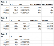
Now running THD for 3 RF's: 27k, 33k, 100k we get the results in table 1.
As you can see, the distortion increases proportionately (well almost) to closed loop gain as predicted by the mechanism described in my previous post.
Now, following negative feedback amplifier theory, you can get around the loss of loop gain by scaling C7 to keep the cross-over frequency Fc constant (and thus the loop gain over frequency). See table 2.
Re-running the experiment, THD can be kept the same at ~ 0.003-4% for all 3 gains by scaling C7 which keeps the loop gain constant. See table 3.
Bottom line, theory works. By understanding the mechanism that causes the distortion, you can make modifications to the amplifier to get the same results; in this case get the same level of distortion regardless of closed loop gain.
BTW, not sure if you guys are following my video series, but if you are not take a look: YouTube
Enjoy!
- Sandro
Parameters are kept constant:
- Pout = 150W_RMS into 8ohms, Vout = 49Vp or 34.5VRMS (Scaled Vin to do this)
- Freq = 20k
- RG = 820
Now running THD for 3 RF's: 27k, 33k, 100k we get the results in table 1.
As you can see, the distortion increases proportionately (well almost) to closed loop gain as predicted by the mechanism described in my previous post.
Now, following negative feedback amplifier theory, you can get around the loss of loop gain by scaling C7 to keep the cross-over frequency Fc constant (and thus the loop gain over frequency). See table 2.
Re-running the experiment, THD can be kept the same at ~ 0.003-4% for all 3 gains by scaling C7 which keeps the loop gain constant. See table 3.
Bottom line, theory works. By understanding the mechanism that causes the distortion, you can make modifications to the amplifier to get the same results; in this case get the same level of distortion regardless of closed loop gain.
BTW, not sure if you guys are following my video series, but if you are not take a look: YouTube
Enjoy!
- Sandro
Attachments
Last edited:
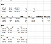
Added Phase Margin and Gain Margin to table 2. Phase Margin is 85 - 90 degrees and GM > 10dB in all 3 cases, so stability is not compromised by the changes in C7 shown in table 2.
Finally, I am using v2.4 of the schematic which I believe is the latest.
Also, I used RF=27k as the nominal case, and scaled from there.
What I did not do, and should have done, is to change R3 to match RF (R6) in each run. Did not do it since I wanted to just change 1 parameter between runs. Table 4 shows the results of also changing R3. As you can see, minimal changes in THD. This should not be a surprise since at 20KHz, R3 is shorted out by C1 and R2, so the effect is minimal.
Enjoy!
- Sandro
Attachments
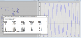
That's interesting, my running of HB with +/-75V PS and 1.5V AC input shows 3.12% distortion at 10kHz with R=43k. See attachments. Am I doing something wrong here?
cheers,
PS thanks sandrovh for the link to Tian method. I hope to master it sooner or later.
cheers,
PS thanks sandrovh for the link to Tian method. I hope to master it sooner or later.
Attachments
Hi Janusz, I tried to run your setup, but it is telling me that it is missing all the XXX_CORDELL models. I think that is the old nomenclature for Bob's models since the newest set are XXXC. But I honestly don't know.
I managed to get the following conditions from your setup
- Vin=1.5Vp
- Fin=10KHz
- VSUP = +/-75V
- RF=43k
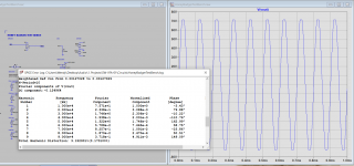
and was able to replicate the results in mine. I got about the same level of distortion 3.152901%. See screenshot 1 for results.
Looking at the output waveform, you can tell what is going on, you are clipping the output. Let's do a bit of analysis:
RF=43k => G=~52 (includes filter attenuation of 27k/27.82k)
Vin=1.5Vp => Vout = 78Vp
You cannot do a 78Vp output with 75V supplies.
If we bump the supplies to 85V, with the same conditions, distortion drops to 0.001764%.
Now, to be ultra cool, let's scale C7 to recover BW. With C7=27k/43k*100p = ~60p, we get a new distortion level of 0.001434%. Not a huge reduction, but something.
Anyway, mystery solved.
Best, Sandro
I managed to get the following conditions from your setup
- Vin=1.5Vp
- Fin=10KHz
- VSUP = +/-75V
- RF=43k
and was able to replicate the results in mine. I got about the same level of distortion 3.152901%. See screenshot 1 for results.
Looking at the output waveform, you can tell what is going on, you are clipping the output. Let's do a bit of analysis:
RF=43k => G=~52 (includes filter attenuation of 27k/27.82k)
Vin=1.5Vp => Vout = 78Vp
You cannot do a 78Vp output with 75V supplies.
If we bump the supplies to 85V, with the same conditions, distortion drops to 0.001764%.
Now, to be ultra cool, let's scale C7 to recover BW. With C7=27k/43k*100p = ~60p, we get a new distortion level of 0.001434%. Not a huge reduction, but something.
Anyway, mystery solved.
Best, Sandro
Attachments
Last edited:
Yes, of course but my intention was to show that with +/-80V supply (with 5V drop we get +/-75V) amp gets into clipping with 1.5V input which is on the low side of a typical CD player output. Most active preamps with such input will give 3-5 times larger output. So what's the point in increasing gain?
My preamp's linear gain (CD input) is only 3.5 so CD output goes to 5-7V. That's why my HB and other amps have gain set to about 28 or 30. Still a lot and amps get into clipping with pot set to just past 12 with +/-64V PS and 625VA toroids.
cheers,
My preamp's linear gain (CD input) is only 3.5 so CD output goes to 5-7V. That's why my HB and other amps have gain set to about 28 or 30. Still a lot and amps get into clipping with pot set to just past 12 with +/-64V PS and 625VA toroids.
cheers,
So what's the point in increasing gain?
It depends to what sensitivity you are designing to. I like to design to consumer 0dBV reference or 1VRMS (1.414Vp).
If you are designing for a 1VRMS (1.414Vp) sensitivity, with RF=40k (not 43k) and 75V PSU (80V - 5V drop), you get 0.001602% of THD at 10k. This is quite ok.
Of course this gain level will not work for higher input levels like 5-7Vp. If you are designing for this input level, then you definitely need less gain.
Since Baracuda did not specify the source, I assumed the consumer 0dBV reference level (1VRMS) in my suggestion.
Wikipedia has a nice article on line levels here:
Line level - Wikipedia
Cheers, Sandro
If you have not mastered the Tian method, check this video.
Sandro, can you upload the HB asc file you are using for the last part of your video?
I'm not sure if it's the same I have.
Thanks!
Carlos
Hi Carlos, you can follow my video series in my thread. I upload a video every two weeks:
SW-VFA-01: Audio power amplifier video series
Also, all the files are posted there.
Best, Sandro
SW-VFA-01: Audio power amplifier video series
Also, all the files are posted there.
Best, Sandro
Last edited:
Of course of one has only sources and a preamp with 1V max output then amp's gain must be adjusted accordingly. The only advantage of having reduced nfb / higher gain is improved 3D imagining but changing gain from 40 to 50 would improve imagining substantially.
cheers,
cheers,
- Home
- Amplifiers
- Solid State
- diyAB Amp The "Honey Badger" build thread