Sorry, what do you mean by that? I can imagine almost anything 🙂....but changing gain from 40 to 50 would improve imagining substantially.
Best regards!
Sorry, what do you mean by that? I can imagine almost anything 🙂.
Best regards!
Sorry, I missed question mark at the end of the sentence. It should read: "...but changing gain from 40 to 50 would improve imagining substantially???"
My guess is it would not but to be sure one would have to check it.
Maybe bacaruda could check it by using 33k and then 43k nfb resistors in his HB and ten listen to his speakers attentively.
cheers,
Last edited:
As has been shown by sandrohv previously, with tweaking the compensation cap accordingly the THD figures won't be altered. So why should amps with different gain values sound differently?
Best regards!
Best regards!
Hi Carlos, here you go.
Best, Sandro
Sandro,
Do you have another asc version ready for sim, with all the settings loaded?
I can't seem to make this version work with the settings I used on another DIYA-amp-LT.
This is the version I have. Is that the version corresponding to the pcb being sold?
Attachments
Sandro,
Do you have another asc version ready for sim, with all the settings loaded?
I can't seem to make this version work with the settings I used on another DIYA-amp-LT.
This is the version I have. Is that the version corresponding to the pcb being sold?
Hi Carlos, what do you mean with all the settings loaded? You mean the input sources, the supplies, the load, etc included?
If that is what you mean, then no. By principle, I do not include those in the schematic of an amplifier. I like to keep my amplifier schematics as clean as possible. I include the sources, load, etc. in a test bench schematic along with the amplifier symbol. This is considered best practice in industry which sadly almost nobody in this forum follows.
I actually started with the schematic you just posted, then I stripped it of all the simulation stuff, verified it against the BOM Excel (and corrected it) and finally created a symbol.
Attached in my Honey Badger test bench along with 'cleaned' version of the amp (see zip file). To understand how to use my test bench, see this video:
YouTube
If you have any questions, just post them.
Best, Sandro
Attachments
Last edited:
Hello there. I would like to ask whether 0.4 c/w heatsinks are sufficient for the honey badger. I am planning to use this enclosure: Mini Dissipante 3U 300mm frontale 10mm NERO coperchi in alluminio 2mm e retro 3mm
Hi Carlos, what do you mean with all the settings loaded? You mean the input sources, the supplies, the load, etc included?
If that is what you mean, then no. By principle, I do not include those in the schematic of an amplifier. I like to keep my amplifier schematics as clean as possible. I include the sources, load, etc. in a test bench schematic along with the amplifier symbol. This is considered best practice in industry which sadly almost nobody in this forum follows.
I actually started with the schematic you just posted, then I stripped it of all the simulation stuff, verified it against the BOM Excel (and corrected it) and finally created a symbol.
Attached in my Honey Badger test bench along with 'cleaned' version of the amp (see zip file). To understand how to use my test bench, see this video:
YouTube
If you have any questions, just post them.
Best, Sandro
The settings I'm referring about are those that allow you to run the simulation, the parameters. The asc file you enclosed does not allow me to do that.
The one I sent you just load it and run it.
I'm not sure if both schematics, mine and yours, are the same.
Hi Carlos, what you are referring to with "those that allow you to run the simulation" are not called settings. They are:
- Spice directives (Simulation commands, parameters, simulator options, etc.)
- Input stimuli (input sources including DC, AC, sine waves, steps, etc)
- Probes (e.g. Tian probe)
- Supplies
- Load
Settings are what you get when you press the "Hammer icon" in the top menu (fourth button on the top row, right next to "Save").
My amplifier schematic, which has been matched to the BOM Excel that you can find here: The diyAB "Honey Badger" Class AB Power Amp - 150W/Channel – diyAudio Store
does not contain any spice directives, input stimuli, supplies, etc. This is on purpose.
The reason I don't include them is because I use a test bench schematic to do all the tests, and all the simulation commands, sources, etc. are placed there. This way I can test many different amplifiers with a single setup. Also this is industry best practice.
If you want to just load and run, use the schematic called "HoneyBadgerTestBench.asc" located in the same zip file. You can find how to use it in the video I pointed you to in post #3805.
Finally the amplifiers in the two schematics are the same , what is different is that yours includes all the stuff I removed (sources, spice directives, etc.) If you disagree please point out differences beyond these.
I hope that clears any confusion.
Best, Sandro
Can I try other amplifiers in your test bench schematic?
The project I'm working on is Luxman 5M21 clone, which was a very successful commercial product in the '80s and to my ears still remains modern and exciting today, beating more expensive designs that came along.
My philosophy is to make designs that were recommended commercial products. In this case the Luxman is an amplifier that I have listened to many times, because a friend of mine that makes high quality speakers uses as his reference amp for his tests.
Of course I would like to compare it with other designs, like the HB, though it implies a serious investment to get one.
I already have the asc files that I have use to simulate it, with remarkable results.
Of course that I'm now using modern devices, as the all those used on the original amp are not available anymore.
The good thing is I will have the original Luxman amplifier to compare my clone to, and see what are the differences, which certainly will have.
This was the thread I did open some time ago to deal with my clone project. Which I don't think is really a clone.
When a Luxman clone is not a clone
When a Luxman clone is not a clone
Hi Carlos, you can any amplifier in my test bench. To use it, you need to do the following pre-work:
- Create a symbol for the amplifier - All you have to do really is copy my symbol for the HB and rename the file name to match your amplifier's file name.
- Rename the pins of your amplifier to match the symbol or rename the symbol pins to match your amplifier (I recommend the former). My symbol uses 4 pins: VIN (Input), VOUT (Output), VCC (+ve supply) and VEE (-ve supply). All 4 pins need to be present.
- Clean the schematic of the amplifier: Remove any simulation commands and voltage sources.
- Place your new amplifier in the test bench.
Extra credit: If you want to run loop gain sims, then
- Amplifier instance name in the top level: XT
- Place a loop gain probe (also included in my zip file) with instance name LGS inside the schematic of the amplifier at the appropriate node.
If you run into trouble, let me know.
Best, Sandro
Hello all, after a couple of weeks having fun building the badger it is now time for testing.
Building a nice chassis will follow after some time when I have listened to my whole collection 🙂.
As a tube guy it is some getting used to the tightness of the sound, but I am impressed. Thanks to OS and the community for developing and supporting this nice amp!
Some pics


Building a nice chassis will follow after some time when I have listened to my whole collection 🙂.
As a tube guy it is some getting used to the tightness of the sound, but I am impressed. Thanks to OS and the community for developing and supporting this nice amp!
Some pics
Last edited:
Honey Badger
Well... with everything going to pot with this covid-19 thing, I decided to start the Honey Badger build and stay out of harms way. So far I've etched the boards with the v2.4 foil posted in this link. Hope everyone stays safe.
Ralph
Well... with everything going to pot with this covid-19 thing, I decided to start the Honey Badger build and stay out of harms way. So far I've etched the boards with the v2.4 foil posted in this link. Hope everyone stays safe.
Ralph
Well... with everything going to pot with this covid-19 thing, I decided to start the Honey Badger build and stay out of harms way. So far I've etched the boards with the v2.4 foil posted in this link. Hope everyone stays safe.
Ralph
Attachments

Hello all, after a couple of weeks having fun building the badger it is now time for testing.
Building a nice chassis will follow after some time when I have listened to my whole collection 🙂.
As a tube guy it is some getting used to the tightness of the sound, but I am impressed. Thanks to OS and the community for developing and supporting this nice amp!
Some pics
Nice work!
What is the output transistors?
Nice work!
What is the output transistors?
Thanks!
The output transistors are MJW3281A / MJW1302A.
Thimios,
according to the build guide you can use a considerable bunch of different power devices, beginning with 2SA1943/2SC5200's for lower rail voltages and 8 ohms load, up to those beefy, double die MJL4281A/4302A's for higher votages and/or 4 ohms load.
Ostripper's design really excels in being very versatile in chosing suitable devices 😉.
Best regards!
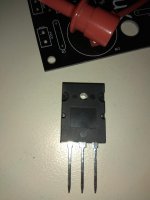
Yes i know but i couldn't recognise those that was used.
Different package?
Sorry, i see now, MJW1302A, not MJL
Different package?
Sorry, i see now, MJW1302A, not MJL
Attachments
Last edited:
I think that you will add a protection system!
I see expensive speakers,don't trust semiconductors...
I see expensive speakers,don't trust semiconductors...
I think that you will add a protection system!
I see expensive speakers,don't trust semiconductors...
You are very right.
For test I installed very fast fuses (500mA) between the amp and speakers. Currently building the protection circuit.
- Home
- Amplifiers
- Solid State
- diyAB Amp The "Honey Badger" build thread