Just found a tool to migrade from LTSpice to Kicad (i'm collecting info before actually porceeding and before i decide which tool to use): GitHub - laurentc2/LTspice2Kicad: LTspice to Kicad schematic conversion
AFAIK, qucs does provide tube symbols. In gschem, i did not find any, and in Kicad it looks as if they could at least be imported. LTSpice provides a few generic symbols for tubes, and the tube models are adapted to them.
AFAIK, qucs does provide tube symbols. In gschem, i did not find any, and in Kicad it looks as if they could at least be imported. LTSpice provides a few generic symbols for tubes, and the tube models are adapted to them.
Quick step forward: i tried the translate2geda tool. Does useful work, but requires dedicated symbols. A limited set of symbols is supplied, but as expected it is far from complete. For example, generic JFETs and of course also tubes are missing.
Anyway, encouraging. (a repository of user contributed symbols might be helpful..)
How Do others deal with this?
Anyway, encouraging. (a repository of user contributed symbols might be helpful..)
How Do others deal with this?
After a bit of exploration of gschem + ngspice my impression is that
- LTSpice is faster.
The above simulation with that simple old tube model took surprisingly long compared to what i intend to do.
- gschem is "just" a schematic editor, admittedly a really nice one.
Do i see correctly that i *MUST* use the command line in order to produce the netlist and to script and start ngspice? No way to embed it into or attach it to the schematic like in LTSpice's editing shell? And ntspice uses its builtin gnuplot and not the good old standalone tool?
If that's really true gEDA will remain the niche product it always was :-(
While i am old fashioned enough to be able to live with that - the typical young GUI user will feel miserable on that. Regardless of the chances that opens - using other simulators (Xyce, Gnucap) where appropriate, for example.
LTSpice is a lot more comfortable in this respect.
BTW: Qucs without "studio" is an active project, open source, supports ngspice and xyce - have a look at source code mirror: GitHub - Qucs/qucs: Qucs Project official mirror
Yes, indeed - and the dev team of qucs has forked a different branch named qucs-S that provides exactly those features.
I'm going to evaluate its possibilities as well.
...
- LTSpice is faster.
...
- gschem is "just" a schematic editor, admittedly a really nice one.
...
LTSpice is a lot more comfortable in this respect.
Maybe LTSpice is on some kind of simulations faster, but cannot be automated. I have presented simulations of a complete amplifier which shows you many different tran and ac results, GM, PM, SOA, etc. in ONE run - without any mouse move (have you ever heard about carpal tunnel syndrome - CTS).
With scripting you can make use of your 16 or 32 prozessors your modern workstation has and you can run many ngspice sims parallel as long as you have enough memory. At least one of my examples I've shown here includes a script which starts ngspice parameter stepping in parallel. Very fast! That makes fun!
My 0.02 EUR:
- gschem, KiCAD and other frontends. The title of this thread is "using and installing ngspice". And even if gschem is old fashioned - a symbol of e.g. a "pentode" is generated in a few minutes.
- LTSpice usability: Don't forget this is currently freeware but after aquisition LT by AD who knows how long a Linux user can use it for free. Have you seen the many encrypted spice models delivered with LTSpice? In other words: the fact that LTspice is running under wine has made it easy to NOT support the open source community developing a free schematic editor which is at least as good as LTspice's editor.
BR, Toni
Last edited:
Hi,
don't get me wrong. I am diskussing this from 2 viewpoints:
a) my own one. A bit lazy, but long Unix experience, and i still do a lot of work in "1000 xterm windows cluttered on the screen". I would even use NetBSD or actually prefer it if there were not a few flaws - lack of usable web browsers and - more important limited support of multiprocessors and a limitation on 2 channels in the usb sound card driver.
So i could live with gschem+ngspice (or Xyce or...) . I am even willing to share as soon as i have something i could share. After some progress in my learning curve.
(under wine i have set up both LTspice 17 and LTSPice 4, and i even would dare to test that on ReactOS which is an open source attempt to do an NT compatible system, and i tend to stick to the old version).
b) the perspective of typical GUI user, be it windows, MacOS or something Ubuntu+fully fledged GUI. That kind of user will be frustrated by gEDA+ntspice, and that has been my critical point. But if some people want to set up a real alternative to LTSpice that would require a more integrated front end, maybe Kicad or qucs-S which is the qucs variant with the ability to use ngspice for simulations. And many of these users are not deep enough in simulation as to be willing to make their own symbols.
I am currently simply evaluating these possible frontend tools to ngspice ... btw, do You know if the GUI of gschem can be extended with guile macros? A minimum solution would be just to add a few menu entries for netlist building and spicing. Already that would make "standard tasks" a lot easier.
BTW: maybe it is useful to fork the discussion on front ends into another thread which also makes it easier to discuss possible alternatives to ngspice (in their own threads...)
BR
Beate
Last edited:
Hi Beate,... btw, do You know if the GUI of gschem can be extended with guile macros? A minimum solution would be just to add a few menu entries for netlist building and spicing. Already that would make "standard tasks" a lot easier.
AFAIK you can extend gschem using the built in scripting language:
geda:guile_scripting [gEDA Project Wiki]
BR, Toni
Now KiCad has the possibility to run NgSpice from EESchema, so it is possible to run DC Sweep, AC and Transient Analysis. However it is not possible to have use of all the advantages of NgSpice.
I have tried using KiCad-generated netlist to Spice (*.cir) and running NgSpice with this netlist. It works fine, but KiCad for some rason add a / before net labels (global net labels work fine).
I agree that (even with the simple NgSpice GUI), you'll have to use commands a typical windows user don't like. So as bea (Beate?) points out, a simple GUI eliminating some of the most used commands would be helpful.
There is a small tutorial using KiCad/Eeschema for schematic capture and external ngspice for simulation. Please see KiCad Eeschema as GUI for ngspice, tutorial for setting up the simulation.
It works fine, but KiCad for some rason add a / before net labels (global net labels work fine).
I will ask the KiCad developers to not do this anymore. If / was replaced by _, data handling in ngspice would be much easier.
bug report to KiCad
I have filed a bug report at Bug #1821502 “Don't use / in netlists for ngspice, use _ instead...” : Bugs : KiCadI will ask the KiCad developers to not do this anymore. If / was replaced by _, data handling in ngspice would be much easier.
There is a way to use KiCad for schematic capture and then external ngspice for simulation, described in KiCad Eeschema as GUI for ngspice, tutorial for setting up the simulation . This might help to have a GUI, but then also the complete spectrum ngspice might offer.
Still we have to wait for the above mentioned bug to be fixed. I will keep you updated.
Still we have to wait for the above mentioned bug to be fixed. I will keep you updated.
With scripting you can make use of your 16 or 32 prozessors your modern workstation has and you can run many ngspice sims parallel as long as you have enough memory. At least one of my examples I've shown here includes a script which starts ngspice parameter stepping in parallel. Very fast! That makes fun!
Hi,
I have 32 thread xeon , do you have more information for this scripting ?
I have already been interested in NGSPICE some time ago but I have not managed to reproduce the simulations I was doing under LTSPICE because of incompatible model or lack of OP measurement function
but since you use it I could persevere 😀
ngspice / Discussion /
ngspice-users:meas OP and max dissipation ?
Unfortunately you can't use models which are calculating values like:
As far as I can see the VDMOS development in ngspice the temperature dependencies are better simulated in the upcoming release so such calculations in model parameters are not needed any more.
Holger please correct me, if I'm completely wrong.
Attached a ngspice helper script, where you can convert model parameters to a fixed temp value. Theoretically you can change model parameters during runtime using the control command "altermod".
and the output...
I'm sure your circuit can be simulated successfully with ngspice if the model library has been modified a little bit.
BR, Toni
.model IRF610 VDMOS ( Rg=5 Vto={4.30-6m* ( 0+temp-25 ) } Lambda=3m Rs={35m* ( 1+3.5m* ( 0+temp-25 ) ) } ...
even it it is allowed from ngspice-30 manual (page 54 / 2.8.2 Brace expressions in circuit elements"). Bug?
As far as I can see the VDMOS development in ngspice the temperature dependencies are better simulated in the upcoming release so such calculations in model parameters are not needed any more.
Holger please correct me, if I'm completely wrong.
Attached a ngspice helper script, where you can convert model parameters to a fixed temp value. Theoretically you can change model parameters during runtime using the control command "altermod".
Code:
toni@tnserver01:~/simulations> cat example_conv_model_params.sp
.param TEMP=40
.param Tjp=TEMP
*.model 20N20_Tjp VDMOS ( Rg=30 Vto={0.155-1.6m* ( Tjp-25 ) } Rs={0.12* ( 1+2.5m* ( Tjp-25 ) ) } Kp={2.40/ ( 1+7.4m* ( Tjp-25 ) ) } Ksubthres={0.09* ( 1+1m* ( Tjp-25 ) ) } Mtriode=0.3 Rd=0.16 Lambda=3m Cgdmax=200p Cgdmin=10p a=0.25 Cgs=1200p Cjo=2200p m=0.7 VJ=2.5 IS=8.0E-6 N=2.4 mfg=IH150521 )
.control
        * calculate fixed values for a specific temp
        *.model 20N20_Tjp VDMOS ( Rg=30
        let Tjp=40
        let Vto={0.155-1.6m* ( Tjp-25 ) }
        let Rs={0.12* ( 1+2.5m* ( Tjp-25 ) ) }
        let Kp={2.40/ ( 1+7.4m* ( Tjp-25 ) ) }
        let Ksubthres={0.09* ( 1+1m* ( Tjp-25 ) ) }
        * Mtriode=0.3 Rd=0.16 Lambda=3m Cgdmax=200p Cgdmin=10p a=0.25 Cgs=1200p Cjo=2200p m=0.7 VJ=2.5 IS=8.0E-6 N=2.4 mfg=IH150521 )

        print vto rs kp ksubthres
.endc
Code:
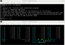
toni@tnserver01:~/simulations> ngspice example_conv_model_params.sp
 ******
** ngspice-30+ : Circuit level simulation program
** The U. C. Berkeley CAD Group
** Copyright 1985-1994, Regents of the University of California.
** Please get your ngspice manual from [URL="http://ngspice.sourceforge.net/docs.html"]Ngspice, the open source Spice circuit simulator - Documentation[/URL]
** Please file your bug-reports at [URL="http://ngspice.sourceforge.net/bugrep.html"]Ngspice circuit simulator - Reporting Bugs[/URL]
** Creation Date: Tue Apr  2 19:01:18 UTC 2019
******
max line length 295, max subst. per line 4, number of lines 32
test temperature 0.000000

vto = 1.3100000e-01
rs = 1.2450000e-01
kp = 2.1602160e+00
ksubthres = 9.1350000e-02
ngspice 9894 ->BR, Toni
Last edited:
It is not possible to use temperature, voltages and currents in model parameter expressions. Correct is that you can use altermod statement between simulation runs to have parametrisized analysis.
The git development branches vdmos_thermal and vbic_thermal will allow to cover self-heating and also change of ambient temperature inside simulation run. The concept is same as we have in bsim4soi and hsim_hv models.
The git development branches vdmos_thermal and vbic_thermal will allow to cover self-heating and also change of ambient temperature inside simulation run. The concept is same as we have in bsim4soi and hsim_hv models.
Thx for info! I have done a merge of ngspice pre-master, vbic and vdmos for myself to simulate my newest amplifier. The sims run good so far.
Hopefully a ngspice 31 version with these self heating features for vbic and vdmos models will arrive soon. 🙂
BR, Toni
Hopefully a ngspice 31 version with these self heating features for vbic and vdmos models will arrive soon. 🙂
BR, Toni
I just restart my archlinux and updated, I'll try this weekend
do you have more information for parallel simulation with ng ?
thanks
do you have more information for parallel simulation with ng ?
thanks
Attachments
Last edited:
In fact it is possible to use temperature, voltages and currents in model parameter expressions. There was a bug in the parser for the VDMOS model. I have pushed a fix to branch pre-master.
You will need to enable PS compatibility.
The following test seems to be o.k.:
Concerning the self heating models, we still have some discussions about the final implementation.
Holger
You will need to enable PS compatibility.
The following test seems to be o.k.:
Code:
VDMOS output

m1 d g s IRF610

*.model IRFZ48Z VDMOS (Rg = 1.77 Vto=4 Rd=1.85m Rs=0.0m Rb=3.75m Kp=25 Cgdmax=2.1n Cgdmin=0.05n Cgs=1.8n Cjo=0.55n Is=2.5p tt=20n mfg=International_Rectifier Vds=55 Ron=8.6m Qg=43n)

.model IRF610 VDMOS ( Rg=5 Vto={4.30-6m* ( 0+temp-25 ) } Lambda=3m Rs={35m* ( 1+3.5m* ( 0+temp-25 ) ) }

vd d 0 1
vg g 0 1
vs s 0 0

Bvt0 1 0 v = 4.30-6m* ( 0+temp-25 )
Bt1 2 0 v=temper
Bt3 3 0 v=temp

.dc vd -1 15 0.05 vg 3 10 1

.control
set temp=25
run
print v(1)[0] v(2)[0] v(3)[0]
showmod
plot vs#branch ylimit -5 15
set temp=80
run
showmod
plot vs#branch ylimit -5 15
.endc

.end
Concerning the self heating models, we still have some discussions about the final implementation.
Holger
...
do you have more information for parallel simulation with ng ?
...
=> here is a shell script example which forks as many ngspice processes parallel as you have processors: Installing and using ngspice - an opensource simulator
BR, Toni
- Home
- Design & Build
- Software Tools
- Installing and using ngspice - an opensource simulator