Perhaps because the .FOUR analysis code was written by Larry Nagel in 1973 and the FFT analysis code was written by Mike Engelhardt in 2005?
Is Mike still in charge or has he transferred the support completely to Analog Devices ?
Hans
Hans
Hi Guys
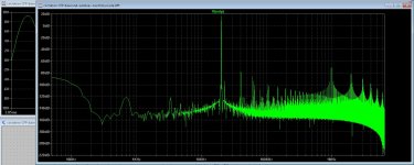
I have simulate a amp, see that the distortion plot on high frequencies is very bad looking.
I have set timestep to 10 nS does make it much better.
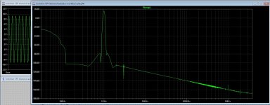
The 1 Khz plot is much better, so I do maybe something wrong, someone now how to setup the best way for FFT to get clean readout,s?
One pic is the 25Khz plot and the much better one is 1Khz. Maybe even there are oscillations, but plot on 10nS is much cleaner on 25Khz, I did use 1 uS for the 1 Khz, but 25 Khz on that setting see pic, not good...
Thanks for helping..
I have simulate a amp, see that the distortion plot on high frequencies is very bad looking.
I have set timestep to 10 nS does make it much better.
The 1 Khz plot is much better, so I do maybe something wrong, someone now how to setup the best way for FFT to get clean readout,s?
One pic is the 25Khz plot and the much better one is 1Khz. Maybe even there are oscillations, but plot on 10nS is much cleaner on 25Khz, I did use 1 uS for the 1 Khz, but 25 Khz on that setting see pic, not good...
Thanks for helping..
Attachments
Kindly read posts #1873 and 1874 in this thread; it was discussed in March.
Thank you.
Hans
If you do not enable 'Skip initial operating point solution' then all settling should be done when the simulation starts. But, when the simulation has extremely large capacitors that are depending on other circuit parts, especially current sources, settling first it may happen that this is not true.
I do here a RIAA pre-amp that will not simulate under any circumstance, until I remove most current sources and replace then with virtual current sources, also some capacitors need to be smaller, and then it will work.
If I try to simulate the thing with out these measures it produces no usable results, so settling(startup/skip) time is important.
On critical circuits I will lit the circuit settel for at the least 10 waveforms and then do a 20 waveform runtime. If the FFT over the first 10 waves matches the second 10 waves I will take the FFT as valid.
May or may not related, but to make things settle a bit faster use the '.ic' command. Especially pre-filling capacitors can be very useful.
From the LTspice manual: (see also the .savebias command)
The .ic directive allows initial conditions for transient analysis to be specified. Node voltages and inductor currents may be specified. A DC solution is performed using the initial conditions as constraints. Note that although inductors are normally treated as short circuits in the DC solution in other SPICE programs, if an initial current is specified, they are treated as infinite-impedance current sources in LTspice.
Syntax: .ic [V(<n1>)=<voltage>] [I(<inductor>)=<current>]
Example: .ic V(in)=2 V(out)=5 V(vc)=1.8 I(L1)=300m
Last edited:
May also not relate directly to the problem at hand, but one needs to be aware that the simulator is kind of a digitizing process, discrete steps are taken(calculated) to simulate the circuit.
There are many commands/settings that influence this process, these can be used to speed up the process or to enhance precision.
Earlier, a number of these where discussed here and may be worth looking up. Of interest are for instance 'tripdv' and 'tripdt'.
There are many commands/settings that influence this process, these can be used to speed up the process or to enhance precision.
Earlier, a number of these where discussed here and may be worth looking up. Of interest are for instance 'tripdv' and 'tripdt'.
This means LTspice does not find the symbols in the directory it searches.
Check the directory where they are, then check the search paths in the LTspice Control Panel|Sim & Lib search paths dialog panel. The Search Paths should point to the directory where those symbols are.
You must have had an error message, what did it say?
Jan
Check the directory where they are, then check the search paths in the LTspice Control Panel|Sim & Lib search paths dialog panel. The Search Paths should point to the directory where those symbols are.
You must have had an error message, what did it say?
Jan
I have found it, the disc was full, but the asc file was damaged and did need a rebuild.
LTspice can not work very good with a full disc, and give the error some late therefore it can not save anymore and result is that schematic without parts.
I have all parts present, so that was not the problem, I have it working again.
I have setup LTspice to delete the FFT files after close it, I hope this helps.
regards
Attachments

Adding your own subcircuit model to LTXVII pt 1
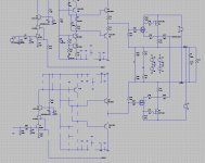
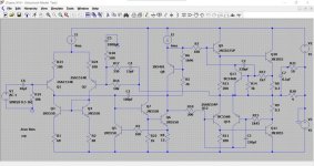
We begin by creating a working simulation using the basic core of the design we wish to have as a model we can call up. This is the attached .asc called 'Subcircuit Model Test'. This is a fully functioning simulation of what will become a model for a 'Chip Amp' that can be called up and dropped into any simulation.
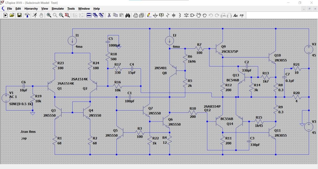
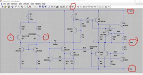
Having got our working circuit we must now go and trim it right down to a 'functional core' which means deleting all unecessary peripherals such as coupling caps and power supplies and so on.
There should be no ground points within the 'core'. If your circuit relies on a ground then you must treat ground as a node or a real pinout on the final model and include it as such when creating the model.
Now we label all connections to the outside world. So for this amplifier we have + and - inputs, a Vcc and Ve for the power supplies and an Output. You can label them whatever you wish as long as you know what they mean.
Use the 'Label Net' button on the toolbar to add these points.
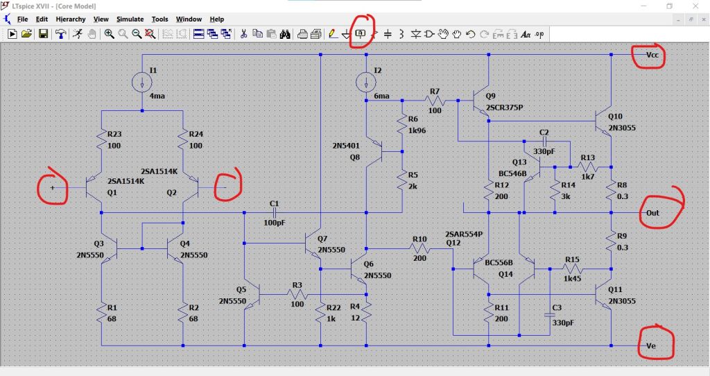
Now you need to decide a name for your model. I'm going to call this 'Chipamp'.
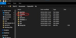
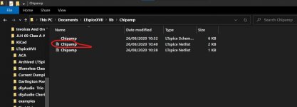
Go to the .Lib folder located in the User LT Spice files. These are the ones LTXVII places in the LT folder in 'Documents'
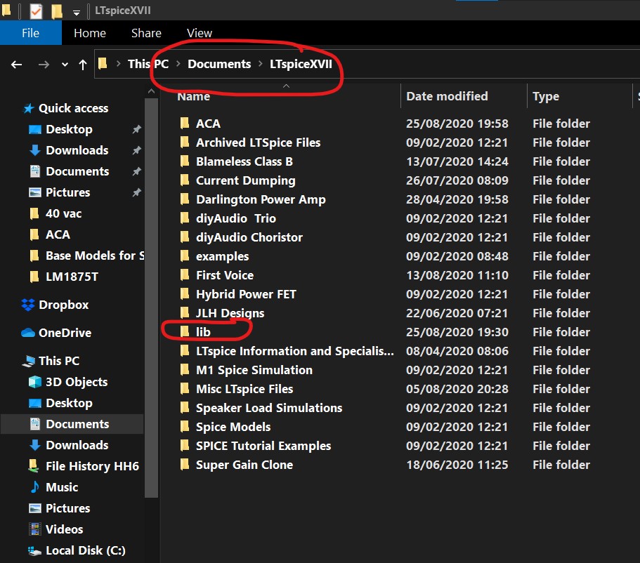
Click on this folder to open it and then add a new folder with your choice of name for the subcircuit.

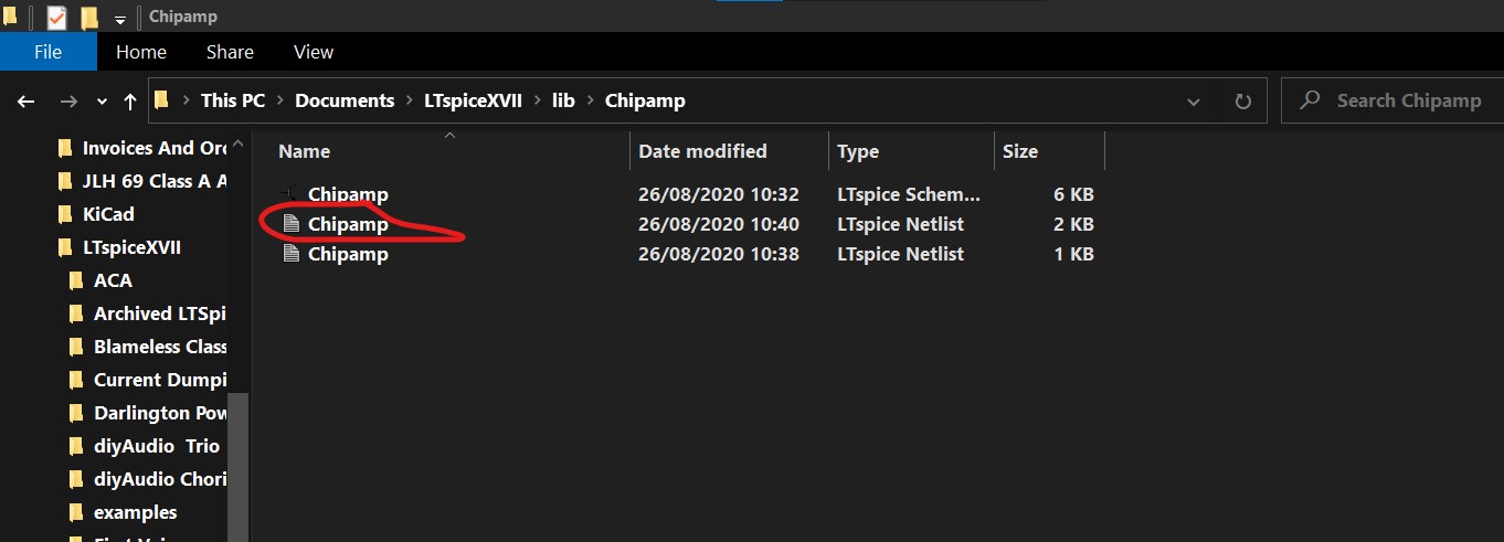
Now having first saved the .asc and then closed LT, go and place the core model .asc into this new folder you have just created.
Be sure to rename the .asc to correspond your chosen name for the model.
So at this point you have a core model of the correct name located in a folder of the correct name located in the Lib user files of LT.
Now click the .asc to open it.
Select 'View' from the toobar followed by 'Spice Netlist' from the dropdown options.
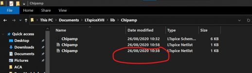
Right click the Netlist and select 'Edit as an independent Netlist'. This opens a 'Save' Window that should enable you to save the file. It will locate by default to the Chipamp folder and appear as a new Netlist alongside the original if you happen to look in that folder. Just leave it as it is.
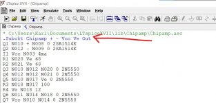
With the Netlist still open in LT we now add a line saying .Subckt Chipamp and then add all the pins we labelled on the core .asc.
We add this new line directly underneath the first line of text.
So we add .Subckt Chipamp + - Vcc Ve Out
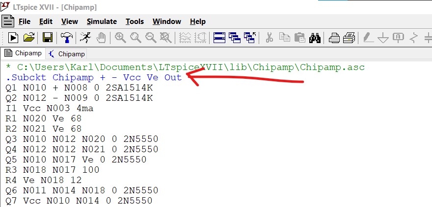
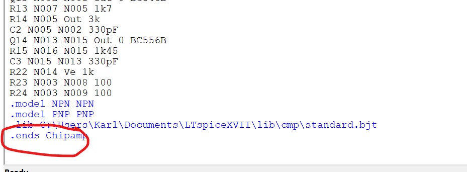
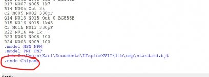
Now delete the last two lines of the Netlist where it says 'backanno' and 'end' and add a new line of .ends Chipamp
We begin by creating a working simulation using the basic core of the design we wish to have as a model we can call up. This is the attached .asc called 'Subcircuit Model Test'. This is a fully functioning simulation of what will become a model for a 'Chip Amp' that can be called up and dropped into any simulation.
Having got our working circuit we must now go and trim it right down to a 'functional core' which means deleting all unecessary peripherals such as coupling caps and power supplies and so on.
There should be no ground points within the 'core'. If your circuit relies on a ground then you must treat ground as a node or a real pinout on the final model and include it as such when creating the model.
Now we label all connections to the outside world. So for this amplifier we have + and - inputs, a Vcc and Ve for the power supplies and an Output. You can label them whatever you wish as long as you know what they mean.
Use the 'Label Net' button on the toolbar to add these points.
Now you need to decide a name for your model. I'm going to call this 'Chipamp'.
Go to the .Lib folder located in the User LT Spice files. These are the ones LTXVII places in the LT folder in 'Documents'
Click on this folder to open it and then add a new folder with your choice of name for the subcircuit.
Now having first saved the .asc and then closed LT, go and place the core model .asc into this new folder you have just created.
Be sure to rename the .asc to correspond your chosen name for the model.
So at this point you have a core model of the correct name located in a folder of the correct name located in the Lib user files of LT.
Now click the .asc to open it.
Select 'View' from the toobar followed by 'Spice Netlist' from the dropdown options.
Right click the Netlist and select 'Edit as an independent Netlist'. This opens a 'Save' Window that should enable you to save the file. It will locate by default to the Chipamp folder and appear as a new Netlist alongside the original if you happen to look in that folder. Just leave it as it is.
With the Netlist still open in LT we now add a line saying .Subckt Chipamp and then add all the pins we labelled on the core .asc.
We add this new line directly underneath the first line of text.
So we add .Subckt Chipamp + - Vcc Ve Out
Now delete the last two lines of the Netlist where it says 'backanno' and 'end' and add a new line of .ends Chipamp
Attachments
-
 Functional Circuit of Model.jpg124.8 KB · Views: 980
 -
 Core Model.jpg120.7 KB · Views: 975
 -
 Lib Folder.jpg175.7 KB · Views: 974
 -
 Lib Folder 2.jpg90.4 KB · Views: 944
 -
 Netlist 1.jpg78.3 KB · Views: 911
 -
 Netlist 2.jpg91.3 KB · Views: 917
 -
 Netlist 3.jpg56.7 KB · Views: 898
 -
 Netlist 5.jpg58.8 KB · Views: 151
 -
 Netlist 4 .jpg70.8 KB · Views: 158
Adding your own subcircuit model to LTXVII pt 2
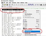
Now scroll back to first line of the Netlist proper (so our line of Subckt Chipamp + - Vcc Ve out) and highlight it.
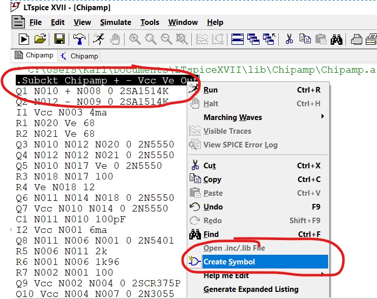
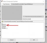
Right click the highlighted line and select 'Create Symbol'. An automatically generated symbol appears with all your named nodes present.
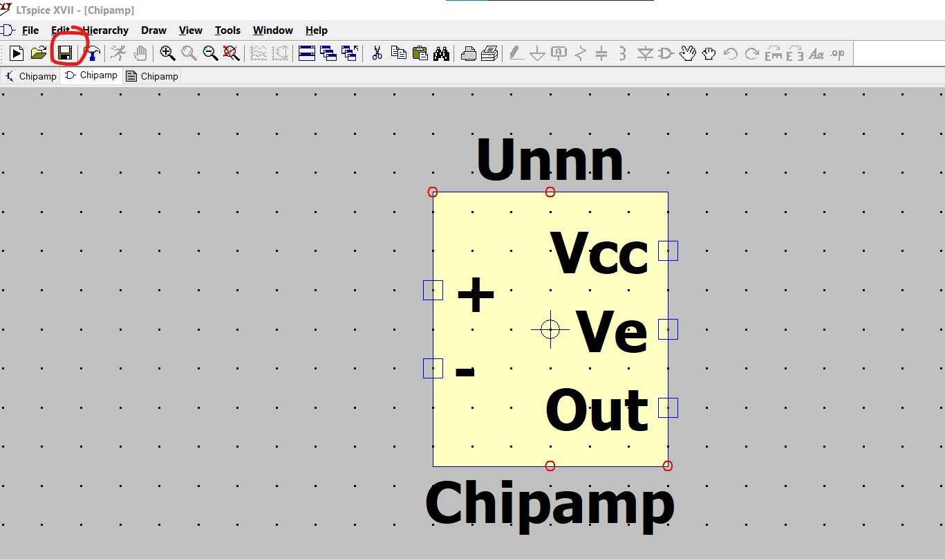
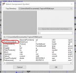
Click 'Save' on the toolbar to save the symbol. It automatically locates to the correct destination which is the 'Auto Generated' folder in the 'Sym' folder.
Now go back to the still open Netlist by selecting it from the top line of open files as shown.
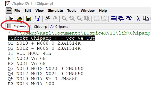
Now save the Netlist. It will appear as before alongside the original. You should know from the times which is which. Delete the old one.

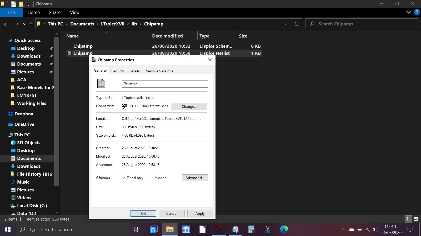
Now right click the new Netlist and in 'Properties' select 'Read Only'. This will prevent LT from ever modifying this file.
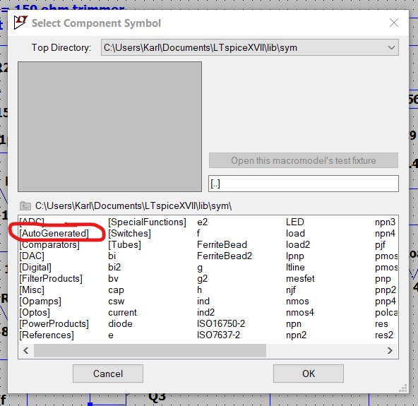
That all being well completes the process. To use the new model simply select 'Auto Generated' from the component selector.

The .asc file of the functional circuit is attached in case anyone wants to practice doing this.
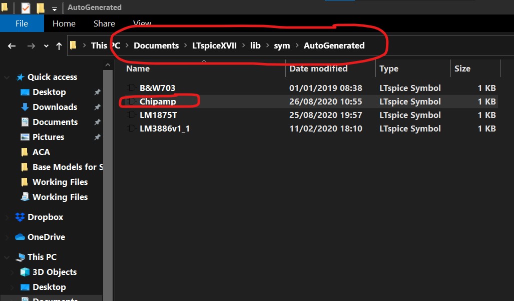
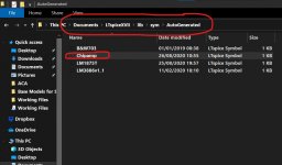
Should you wish to delete the model at any time then remember you have to delete not just the folder you created (Chipamp in the Lib folder in this case) but also the Symbol file which lives in the 'Auto Generated' folder. This is to be found in the Sym folder which is a folder of the Lib. Open the Auto Generated folder and just delete the relevant symbol model.
Now scroll back to first line of the Netlist proper (so our line of Subckt Chipamp + - Vcc Ve out) and highlight it.
Right click the highlighted line and select 'Create Symbol'. An automatically generated symbol appears with all your named nodes present.
Click 'Save' on the toolbar to save the symbol. It automatically locates to the correct destination which is the 'Auto Generated' folder in the 'Sym' folder.
Now go back to the still open Netlist by selecting it from the top line of open files as shown.
Now save the Netlist. It will appear as before alongside the original. You should know from the times which is which. Delete the old one.
Now right click the new Netlist and in 'Properties' select 'Read Only'. This will prevent LT from ever modifying this file.
That all being well completes the process. To use the new model simply select 'Auto Generated' from the component selector.
The .asc file of the functional circuit is attached in case anyone wants to practice doing this.
Should you wish to delete the model at any time then remember you have to delete not just the folder you created (Chipamp in the Lib folder in this case) but also the Symbol file which lives in the 'Auto Generated' folder. This is to be found in the Sym folder which is a folder of the Lib. Open the Auto Generated folder and just delete the relevant symbol model.
Attachments
-
 Symbol 1.jpg154 KB · Views: 895
 -
 Symbol 2.jpg108.4 KB · Views: 872
 -
 Netlist 4 .jpg70.8 KB · Views: 882
 -
 Netlist 6.jpg216.5 KB · Views: 863
 -
 Netlist 5.jpg58.8 KB · Views: 849
 -
 Model Use 1.jpg72.1 KB · Views: 845
 -
 Model Use 2.jpg47.3 KB · Views: 857
 -
Subcircuit Model Test.asc7.7 KB · Views: 170
-
 AutoGenerated.jpg88 KB · Views: 816

What does it mean when some or all harmonics appear to be antiphase to the fundamental?If they are audible , how will they sound or how will they affect the fundamental? I get this response consistently when i parallel some op-amps and buffers .Also the noise and distortion grow although they should both go lower with paralleling devices....which is strange.
This time it's me with a strange problem that I can't explain and never had before.
When running a sim with the following directives (that Jan Didden made me aware of),
.param Freq=10k
.param numcyc=20
.param dlycyc=5
.param FFT=2**16
.param simtime=numcyc/freq+dlytime
.param dlytime=dlycyc/freq
.param timestep=(simtime-dlytime)/FFT
.four {freq} v(out)
.tran 0 {simtime} {dlytime} {timestep}
I get a large discrepancy at this 10Khz between what .four reports and the FFT image.
The FFT shows, see first image below
H1 -10dB = 3.2e-1, corresponding with the RMS signal in the time image
H2 -100dB = 1e-5
H3 -125dB = 6e-7
H4 < -155dB = 2e-8
Via the .fear command I find in the error log
H1 4.5e-1
H2 2.4e-4
H3 1.5e-4
H4 1.2e-4
Even the fundamental is wrong, but look at H4, 1.2e-4 instead of 2e-8.
Doing the same for 1Khz, see second image, .four is still wrong starting with a wrong fundamental, but quite a lot better as at 10Khz, although the FFT's at 10Khz and at 1Khz are practically the same.
What can be the case of these huge discrepancies ?
Hans
I had this weird problem where the FFT deviated a great deal from the outcome of the .Four command.
In just another situation I ran across the same problem and found the solution.
When simply attenuating the signal with a resistance divider until a certain level, all at the sudden all was O.K. between FFT and .Four.
No Idea why, but I'm happy to have found a workaround.
Hans
I see from the truncated FFT output that you are shortening the simulation time using one of the quick methods.. Did you try doing it the long-hand way? I like to leave a simulation run for up to 15 minutes, and sit back with a cup of coffee or a glass of wine.I had this weird problem where the FFT deviated a great deal from the outcome of the .Four command.
In just another situation I ran across the same problem and found the solution.
When simply attenuating the signal with a resistance divider until a certain level, all at the sudden all was O.K. between FFT and .Four.
No Idea why, but I'm happy to have found a workaround.
Hans
I've never needed to run an analog simulation for 15 minutes. Class D however can take a while.
This would have been an ideal test case to report to the developer.
When simply attenuating the signal with a resistance divider until a certain level, all at the sudden all was O.K. between FFT and .Four.
No Idea why, but I'm happy to have found a workaround.
Hans
This would have been an ideal test case to report to the developer.
I reported the original discrepancy problem between FFT and .Four to the developer, but got a message in return that they are too busy doing other things.
Mike Engelhard is no longer there, he certainly would have addressed the problem in a proper way.
Hans
Mike Engelhard is no longer there, he certainly would have addressed the problem in a proper way.
Hans
Mike Engelhard has retired from the company, as far as I know. He has confirmed a rumour that he is independently developing a much better version of the circuit simulation software. It may take him some time.I reported the original discrepancy problem between FFT and .Four to the developer, but got a message in return that they are too busy doing other things.
Mike Engelhard is no longer there, he certainly would have addressed the problem in a proper way.
Hans
Which would mean that a) it will not be free, and b) it may be a few years as Mike must have signed a non-competition clause at some point.
Jan
Jan
- Home
- Design & Build
- Software Tools
- Installing and using LTspice IV (now including LTXVII), From beginner to advanced