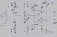
Very Cool Stuff Mooly !!!
Just as a note, I would like to add that for anyone using Linux it does run using WINE as well !! 🙂
FWIW
jer 🙂
Just installed it myself using wine.
Appears to be fully functional
Yay
can somebody help me with two accurate spice models for bd139 and bd140 from a current manufacturer?
I did drawn a high openloop predriver based on the diamond input, using accuphase designs to combine to get idea,s
Hmmm it did oscillate on 5 Mhz of such, but after some tryouts, it seems that the voltage lines need decoupling, resistors and cap,s.
because LTspice does not like these oscillations it is sometimes difficult to find it.
As for short, the cascoded circuits does make high openloop and a nice current feedback give low distortions in LTspice.
By the way no crashes anymore, have other videocard with hardwareacceleration, was needed for pcb program Kicad.
I have a library where the mosfets in it from phillips does no good, these do not work well.
regards
Attachments
Now I have a question about matching models in LTspice.
reason is I have used other transistors and I get uge offsets, is there a reason for this, can it be that also pnp and npn models cause this? I have gordell models from X did try also others all did change that offset and I get it not lower. the 2sc2240 and the 2sa970 did a good job lower offset to just 34 mV.
did enclose schematic for ksc and 2sc type transistor who did now well. see schematic.
Can someone explane that for me, I am very thankfull.
Have a nice day
regards
Attachments
I have found the real reason of crashes and strange behaviors.
The program screentake does induce problems, the update manager of it crashes and I can not use F9 of LTspice when active, have the most strange effects.
It was a search but now I have it, and remove that program, I seek a other good screentake program.
Do you still live here? so quiet.
The program screentake does induce problems, the update manager of it crashes and I can not use F9 of LTspice when active, have the most strange effects.
It was a search but now I have it, and remove that program, I seek a other good screentake program.
Do you still live here? so quiet.
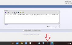
You can also create a shortcut that does that.
Filepath is:
And there are some scissors (for an icon) here:
or for a higher quality full screen image I use the 'PrntScr' key and then paste the image into paint.
Filepath is:
Code:
explorer.exe ms-screenclip:And there are some scissors (for an icon) here:
Code:
%SystemRoot%\System32\shell32.dllor for a higher quality full screen image I use the 'PrntScr' key and then paste the image into paint.
Attachments
I have now installed screenhunter, that one does fine, I did Shift windows key and s, nothing happen.
Screenhunter push F6 and get what you want.
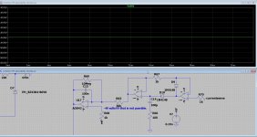
But hee, why I get 49 volts on a place where this is not possible, the opamp has just 12 volt and ref is 350 mV
can ltspice get in trouble if there is a bad model or so?
never see this.
Screenhunter push F6 and get what you want.
But hee, why I get 49 volts on a place where this is not possible, the opamp has just 12 volt and ref is 350 mV
can ltspice get in trouble if there is a bad model or so?
never see this.
Attachments
I have now installed screenhunter, that one does fine, I did Shift windows key and s, nothing happen.
The current build of Windows 10 replaced the old "Snipping Tool" with "Snip & Sketch." The Shift-Windows-S shortcut works for the new Snip & Sketch but not the old Snipping Tool, which has no built-in keyboard short cut. See link below.
https://support.microsoft.com/en-us/help/4027213/windows-10-open-snipping-tool-and-take-a-screenshot
So if you have not updated Windows to the 2004 build then you probably don't have Snip & Sketch, which is why the keyboard shortcut doesn't do anything.
I hope this helps.
I have windows 7, do not like 10.
I have this not installed, did try it.
But i have screenhunter installed, easy, just F6 and reactangle area and save.
Thanks for help appreciate it.
I have this not installed, did try it.
But i have screenhunter installed, easy, just F6 and reactangle area and save.
Thanks for help appreciate it.
Naming Expressions
Is it possibe to give expressions a name and have such displayed in the Waveform Viewer rather than the formula (which could be long)?
Is it possibe to give expressions a name and have such displayed in the Waveform Viewer rather than the formula (which could be long)?
for some, but probably not all calculations, you could define them in a bv, a behavioral voltage source. Then just probe the bv to get the answer.
This time it's me with a strange problem that I can't explain and never had before.
When running a sim with the following directives (that Jan Didden made me aware of),
.param Freq=10k
.param numcyc=20
.param dlycyc=5
.param FFT=2**16
.param simtime=numcyc/freq+dlytime
.param dlytime=dlycyc/freq
.param timestep=(simtime-dlytime)/FFT
.four {freq} v(out)
.tran 0 {simtime} {dlytime} {timestep}
I get a large discrepancy at this 10Khz between what .four reports and the FFT image.
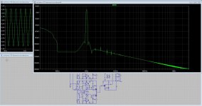
The FFT shows, see first image below
H1 -10dB = 3.2e-1, corresponding with the RMS signal in the time image
H2 -100dB = 1e-5
H3 -125dB = 6e-7
H4 < -155dB = 2e-8
Via the .fear command I find in the error log
H1 4.5e-1
H2 2.4e-4
H3 1.5e-4
H4 1.2e-4
Even the fundamental is wrong, but look at H4, 1.2e-4 instead of 2e-8.
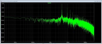
Doing the same for 1Khz, see second image, .four is still wrong starting with a wrong fundamental, but quite a lot better as at 10Khz, although the FFT's at 10Khz and at 1Khz are practically the same.
What can be the case of these huge discrepancies ?
Hans
Attachments
Hans, I noted that the .four can have some specific parameters set:
The Fourier analysis is performed over the period from the final time, Tend, to one period before Tend unless an integer Nperiods is given after Nharmonics. If Nperiods is given as -1, the Fourier analysis is performed over the entire simulation data range.
There may be similar issues with .four as with an FFT if it is not synchronous.
You could try some of the .four settings.
I have no experience with .four, don't use it as it is just for compatibility with older simulator versions, no idea how good it is.
Jan
Last edited:
Can somebody tell me why simulation goes strange, like I get 2 kV output from a opamp or it does give strange hang behavior.
Looks like if amp oscillate it go flipping. What can I do as .op for that stability? some people does set it into schematic to get stable simulations.
sometimes it does oke, I think i need .option cshunt= or so
thanks
Looks like if amp oscillate it go flipping. What can I do as .op for that stability? some people does set it into schematic to get stable simulations.
sometimes it does oke, I think i need .option cshunt= or so
thanks
Last edited:
Jan,Hans, I noted that the .four can have some specific parameters set:
The Fourier analysis is performed over the period from the final time, Tend, to one period before Tend unless an integer Nperiods is given after Nharmonics. If Nperiods is given as -1, the Fourier analysis is performed over the entire simulation data range.
Jan
Thank you for your feedback. I tried several values for Nperiods, but it made the discrepancy even larger.
That's why I have now sent an email to LTspice@analog.com.
When something useful comes out, I will report it back in this thread.
Hans
Hi Guys.
I have a question about a simulation, it is a balanced diamond input driver part for a circlotron, however, if I do simulate it it flips to the supply rail, in this case the negative side, I have to inject 4 or so volts to get it on zero output voltage and as such balanced.
Maybe and I think I am right but still ask for shure, the transistor models are not acting as a paired transistor and does cause the offset unbalance, this driver needs paired transistors on some places.
Maybe there is a way to set ltspice for this.
Thanks and have a nice day.
PS I have now no crashes anymore for some weeks, it was software who cause this, when active I was not enable also to recover changes with F9.
regards
Attachments
In LTspice, (any simulator) if you place two transistors with the same type, they are perfectly identical, much better than any practical matching can achieve.
Unless you deliberately modify the models to make them different.
Jan
Unless you deliberately modify the models to make them different.
Jan
- Home
- Design & Build
- Software Tools
- Installing and using LTspice IV (now including LTXVII), From beginner to advanced

