Hi all
Does somebody has a model for a CD4035A 4 stage shift register.
thanks in advance.
Does somebody has a model for a CD4035A 4 stage shift register.
thanks in advance.
Last edited:
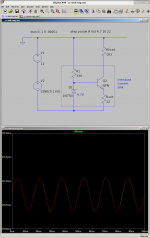
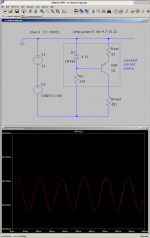
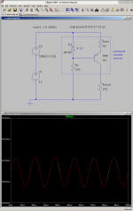
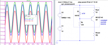
Here are basic positive and negative constant current sinks and sources using zeners and BJTs. I always forget the exact arrangement of the parts, so it is useful to see all four configurations at once for reference.
The voltage source is 12V +/- 1V @ 60Hz, which approximates a filtered but unregulated 12V rail.
The simulation shows that the current through Rload is the same for three different values of Rload (4.7ohm, 10ohm, and 22ohm). It is difficult to tell that this is actually three graphs, because the sine waves are directly on top of one another.
These are useful as a conceptual base to start from, but of course the performance isn't spectacular, because the zener regulation isn't great. From here, you can try to improve the performance (try cascading two zeners, or replacing Rz with a jfet, etc), or try modifying it to use fets, etc.
😀
Attachments
-
cc-source-pos.asc1.2 KB · Views: 106
-
 Screenshot_2020-10-02_19-33-24.png49.1 KB · Views: 269
 -
 Screenshot_2020-10-02_19-38-23.png50.8 KB · Views: 272
 -
 Screenshot_2020-10-02_19-43-19.png48.9 KB · Views: 272
 -
 Screenshot_2020-10-02_19-40-50.png49.7 KB · Views: 264
 -
cc-sink-neg.asc1.2 KB · Views: 125
-
cc-source-neg.asc1.2 KB · Views: 113
-
cc-sink-pos.asc1.2 KB · Views: 100
Instead of the standard pnp transistor, put the real one. The real transistor has the parameter Erlie voltage (VAF). In your case, the VAF is infinity. The smaller the VAF, the more the collector current changes when the voltage between the collector and the emitter changes. The change after changing the transistor will be, but do not expect a large change in current.
Attachments
Last edited:
Hi all
Does somebody has a model for a CD4035A 4 stage shift register.
thanks in advance.
Components Library and Circuits - LTwiki-Wiki for LTspice
Might be one in here.
Incorporating a FQP3P50 P-Channel MOSFET model into my simulation
Hi,
I’m trying to incorporate an FQP3P50 P-Channel MOSFET model into my sim.
I found FQP3P50(LTSPICE MODEL).TXT on onsemi.jp/support and downloaded it (first attachment).
Turns out it’s for a “FQP3D50” but that’s just the surface-mount variant rather than the TO-220. I saved it as FQP3P50.lib, replaced the “D” with “P” in the file and deleted the thermal model stuff. The file is attached.
I copied a P-Channel MOSFET symbol I already had and replaced all occurrences of the existing name with “FQP3P50” (second attachment).
I suspect there’s something I need to do to make sure the pin numbers in the .asy and .lib files match up.
When I run the DC operating point sim I get the unrecognized parameter error in the 3rd attachment.
The final attachment is the zipped model files.
Can someone tell me what I need to do to the FQP3P50 model file please?
Attachments
Hi dch53,
My attached uses the standard IRF9610 as a FQP3P50 stand-in.
You can check the "gm" value in the ErrLog against your model. It's fairly close.
I think your Bsim model is working and you can ignore the FC error message. You can use either model. It's your choice.
BTW I modified your FQP3P50.asy attributes then put the .include on your circuit. This way you place your "FQP3P50.lib" model in the same directory as the circuit file.
Attachments
Hi dch53,
My attached uses the standard IRF9610 as a FQP3P50 stand-in.
You can check the "gm" value in the ErrLog against your model. It's fairly close.
I think your Bsim model is working and you can ignore the FC error message. You can use either model. It's your choice.
BTW I modified your FQP3P50.asy attributes then put the .include on your circuit. This way you place your "FQP3P50.lib" model in the same directory as the circuit file.
Thanks Ian. Happy to use your model. Do you have the model file for the IRF9610 please?
Hi dch53, Sorry I didn't send the IRF9610 model.
I assumed it was a standard LTspice model. But it looks like it is one of Alexander Bordodynov's extras and that what I am using.
His library is available here For LTspice users. Libraries of models, examples, etc .
The link Transistors and diodes, file is cmp.zip ~260K was updated 17 September.
LT-XVII users copy the new 'standard.mos' file into your LTC user directory (NOT the Program files directory) - this means your new 'standard.mos' file doesn't get overwritten when you do a web update.
Code:
.model IRF9610 vdmos pchan VTO=-3.667 RS=0.47274 KP=0.813 RD=1.733 RG=10 Ksubthres=0.1 CGDMAX=4.05E-10 CGDMIN=3.00p Cjo=3.06E-11 IS=6.17e-61 Rb=0.267 TT=1.762e-06 Cgs=1.53E-10 mfg=International_Rectifier Vds=-200His library is available here For LTspice users. Libraries of models, examples, etc .
The link Transistors and diodes, file is cmp.zip ~260K was updated 17 September.
LT-XVII users copy the new 'standard.mos' file into your LTC user directory (NOT the Program files directory) - this means your new 'standard.mos' file doesn't get overwritten when you do a web update.
His library is available here For LTspice users. Libraries of models, examples, etc. The link Transistors and diodes, file is cmp.zip ~260K was updated 17 September.
Thanks again. My model works perfectly now and I can do some more advanced simulations on it.
That's a brilliant resource!
LTSpice Model for ZVP3310A
Hi everyone! 🙂
Can someone please help me with regards to getting the PMOS transistor model (ZVP3310A) to work on LTSpice. The original model from the website doesn't seem to work when integrated into LTSpice and I don't know why because I can't pick up any problems with the file.
*ZETEX ZVP3310A Mosfet Spice Subcircuit Last revision 8/98
*
.SUBCKT ZVP3310A/ZTX 3 4 5
* D G S
M1 3 2 5 5 P3310M
RG 4 2 585
RL 3 5 1E9
D1 3 5 P3310D
*
.MODEL P3310M PMOS VTO=-2.955 RS=9.658 RD=4.9 IS=1E-15 KP=0.322
+CGSO=19E-12 CGDO=3E-12 CBD=35E-12 PB=1 LAMBDA=6.67E-3
*
.MODEL P3310D D IS=5E-12 RS=.768
.ENDS
*
*$
It's a subcircuit not a "LTSPICE model". You'll need to read the LTSPICE Help File section named Third Party Models. It talks about subcircuits and how to use them.
Hi u13056647,
An LTspice (VDMOS) model is available in Alexander Bordodynov's library. See Post 2289 for installing it.
Alternatively paste this in your circuit file:
An LTspice (VDMOS) model is available in Alexander Bordodynov's library. See Post 2289 for installing it.
Alternatively paste this in your circuit file:
Code:
*VDMOS with subthreshold (c) Ian Hegglun
.model ZVP2110G VDMOS (pchan Rg=65 Vto=-2.8 Kp=0.17
+ Rs=2 Ksubthres=0.15 Mtriode=0.5 Rd=2.5 Lambda=6m
+ Bex=-2.3 Vtotc=6m Tksubthres1=4m Trs1=3.5m Trd1=8m
+ Cgdmax=20p Cgdmin=3p a=0.5 Cgs=140p Cjo=50p
+ m=0.5 Vj=0.75 Is=5p N=3 Eg=2.8 Rb=1 Trb1=1m
+ Vds=-100 Ron=8 Qg=2n mfg=DioIncIH1907)Can someone please help me with regards to getting the PMOS transistor model (ZVP3310A) to work on LTSpice. The original model from the website doesn't seem to work when integrated into LTSpice and I don't know why because I can't pick up any problems with the file.
*ZETEX ZVP3310A Mosfet Spice Subcircuit Last revision 8/98
You can use a subcircuit like this instead of a model file, but you will need a different symbol that is not included with LTspice. Attached are PMOS and NMOS symbols that are intended to be used with subcircuits. Note that they have a "x" prefix to denote that they are used with subcircuits.
The forum won't allow .asy files to be uploaded, so these have a .txt extension. Rename these to xpmos.asy and xnmos.asy respectively. I store all of my custom symbols like this in a separate User folder.
I hope this helps.
Attachments
Last edited:
Hello Mooly
I am designing a new amp and naturally I depend on LTSpice for sim and THD measurements.
I hope you do not mind I ask this noob question:
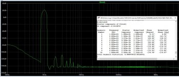
When I perform the FFT analisys I get a graph showing the harmonics but then I select the error log window and the values presented are never consistent with what I see in the graph.
In the image below we see clearly that 2nd harmonic is lower than 3rd but error log indicates the inverse.
Why do these two information do not correlate ?
I am designing a new amp and naturally I depend on LTSpice for sim and THD measurements.
I hope you do not mind I ask this noob question:
When I perform the FFT analisys I get a graph showing the harmonics but then I select the error log window and the values presented are never consistent with what I see in the graph.
In the image below we see clearly that 2nd harmonic is lower than 3rd but error log indicates the inverse.
Why do these two information do not correlate ?
Attachments
I have no quick answer to that without being able to play around with the sim.
Have you got the timestep set correctly and also compression turned off (.option plotwinsize=0)
Have you got the timestep set correctly and also compression turned off (.option plotwinsize=0)
Hello Mooly
Here you have the sim and the models I am using.
Please try with power = 20w and do the FFT.
Error log does not give the same results.
I do need to be sure about the values presented in the error log because I have a spreasheet that I use for comparisons.
Here you have the sim and the models I am using.
Please try with power = 20w and do the FFT.
Error log does not give the same results.
I do need to be sure about the values presented in the error log because I have a spreasheet that I use for comparisons.
Attachments
Yes. I will post the sim asap
You seem to be anything but a noob.
The error log result is less accurate as the FFT, both seem to be made by different persons.
Change the numcyc or dlycyc and the error log will change with it but the FFT will stay the same.
In this case results are close, but sometimes the can be much farther apart.
I wrote Anolog Devices about this anomaly but their response was that they had no resources available to investigate this.
Hans
- Home
- Design & Build
- Software Tools
- Installing and using LTspice IV (now including LTXVII), From beginner to advanced