Beat me to it. One solution is negative so throw it out. But I did not know spice would do it. Cool!
Attachments
Last edited:
Hans I'm sorry but it still escapes me,
Why not take the schematic from
https://www.diyaudio.com/forums/sof...ltxvii-beginner-advanced-222.html#post6311790
It is very simple, why not solve it, for any voltage and any value of R1 as has been shown in the iterating solution.
Why not take the schematic from
https://www.diyaudio.com/forums/sof...ltxvii-beginner-advanced-222.html#post6311790
It is very simple, why not solve it, for any voltage and any value of R1 as has been shown in the iterating solution.
He used the same schematic and added the math. The math I showed in my drawring. And it will solve for any values of V and W you put in.
What im curious about is if spice can figure it out witout the added math. Can you set R2 to be 100/I^2 and I to 100/(R2+10). (Or R2 to 100/(100/(R2+10)^2) Looks like trouble. Guess spice would have to know how to solve simultaneous equations. Anyone ever try anything like this?
Hans, what you really need is SliCap: SLiCAP — Analog Electronics
It works with Matlab, and takes a Spice netlist to do all kind of optimization stuff.
Jan
It works with Matlab, and takes a Spice netlist to do all kind of optimization stuff.
Jan
Hans, what you really need is SliCap: SLiCAP — Analog Electronics
It works with Matlab, and takes a Spice netlist to do all kind of optimization stuff.
Jan
Jan, thanks for the tip, but what does it offer that LTspice does not ?
At first sight there seems to be a large overlap.
And for the solution of the Frans problem, simple mathematics proved to do the job.
Hans
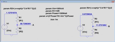
And if still needed, here is a generic solution for the problem.
You can individually enter values in the middle for the voltage source Vin, for R1 and for the Wattage that you want in the second resistor.
Since there are always 2 solutions, these resistors are resp. R2 and R4, left and right.
Hans
You can individually enter values in the middle for the voltage source Vin, for R1 and for the Wattage that you want in the second resistor.
Since there are always 2 solutions, these resistors are resp. R2 and R4, left and right.
Hans
Attachments
Beat me to it. One solution is negative so throw it out. But I did not know spice would do it. Cool!
https://www.diyaudio.com/forums/sof...ltxvii-beginner-advanced-224.html#post6312153
First of all thanks for the effort, but I can not make it work.
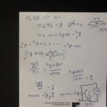
From the solution that was given:
(x*sqrt(b))**2 = (a+b)**2; Note the number 10 replaced by x
Replacing known numbers:
(x*sqrt(4))**2 = (2+4)**2
This can be solved like:
4*(x**2) = 36
x**2 = 9
x = 3
Where:
x = ((a+b)**2)/b
So, the question is:
How to resolve 'x' not knowing 'b'
I did simplify the value names and removed the value equalities.
Attachments

Last edited:
And if still needed, here is a generic solution for the problem.
You can individually enter values in the middle for the voltage source Vin, for R1 and for the Wattage that you want in the second resistor.
Since there are always 2 solutions, these resistors are resp. R2 and R4, left and right.
Hans
Hans, thanks you solved it, cool.
Less simple than wan may expect but a solid numerical solution.
Frans.
Attachments
Last edited:
https://www.diyaudio.com/forums/sof...ltxvii-beginner-advanced-224.html#post6312153
First of all thanks for the effort, but I can not make it work.
From the solution that was given:
(x*sqrt(b))**2 = (a+b)**2; Note the number 10 replaced by x
Replacing known numbers:
(x*sqrt(4))**2 = (2+4)**2
This can be solved like:
4*(x**2) = 36
x**2 = 9
x = 3
Where:
x = ((a+b)**2)/b
So, the question is:
How to resolve 'x' not knowing 'b'
I did simplify the value names and removed the value equalities.
What the hell have you been doing.
All you had to enter were values for Vin, for R1 and for the Power and then run the simulation.
You did not have to solve x and you did not have to solve b, that's what LTspice does for you.
Hans
Last edited:
Hans, thanks you solved it, cool.
Less simple than wan may expect but a solid numerical solution.
Frans.
Ok this one is correct, although only one of the two possible solutions.
Hans
What the hell have you been doing.
All you had to enter were values for Vin, for R1 and for the Power and then run the simulation.
You did not have to solve x and you did not have to solve b, that's what LTspice does for you.
Hans
Sorry, that all was about this one
https://www.diyaudio.com/forums/sof...ltxvii-beginner-advanced-225.html#post6312223
I did add the wrong link.
Last edited:
Weird FFT issue
Hi all.
Inspired by sandro's video 5.2.2, I wanted to get my sim "template" updated for best possible FFT.
I therefore checked and updated all my values to match the one's from his video. I could however not make it match what he shows, when doing FFT on 'VSine'
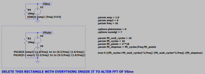
Digging deeper I started to delete different sources and ended up with the following. It's a schematic with a sine wave source and a square wave source.
The square wave source is not connected to anything, but still it seems to alter the FFT result. If I delete what is inside the rectangle, the FFT result for 'VSine' looks just like sandro's ( ~ perfect )
Can anyone explain what is going on?
Regards
Jørgen
PS. Thanks for the video's sandro
Hi all.
Inspired by sandro's video 5.2.2, I wanted to get my sim "template" updated for best possible FFT.
I therefore checked and updated all my values to match the one's from his video. I could however not make it match what he shows, when doing FFT on 'VSine'
Digging deeper I started to delete different sources and ended up with the following. It's a schematic with a sine wave source and a square wave source.
The square wave source is not connected to anything, but still it seems to alter the FFT result. If I delete what is inside the rectangle, the FFT result for 'VSine' looks just like sandro's ( ~ perfect )
Can anyone explain what is going on?
Regards
Jørgen
PS. Thanks for the video's sandro
Attachments


Hans and anyone interested,
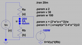
A few days ago I posted a question, I needed to resolve a seemingly simple puzzle (see attached schematic).
After posting the question Hans was so friendly to supply the answer, this quadratic problem escaped my while it looked simple and I never thought of it being quadratic.
The basic mathematics is simple, and the whole ting can be written down as:
i=(v/(a+b)); current in Va
p=((v^2)/(a+b)); power total by Va
q=((i^2)*a); power in Ra
w=p-q; power in b; power in Wb
w=((v^2)/(a+b))-(((v/(a+b))^2)*a)
Where the last line is all that is known about the problem.
As it goes, I was happy with the solution provided by Hans, but if every one with a mathematics problem needs Hans he may be more busy then he would like yo be.
So here is an alternative solution that may be helpful.
Go, using your internet browser, to Wolfram|Alpha: Computational Intelligence and enter the equation in the 'problem'-box, do add the phrase 'for b' as done here below
Enter: w=((v^2)/(a+b))-(((v/(a+b))^2)*a) for b
And enjoy
Regards,
Frans.
Attachments

Last edited:
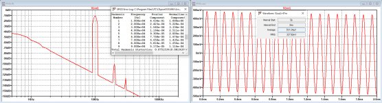
Further to my posting in #2195, I started some further experimenting since Analog Devices replied not to have the resources to help me.
The problem as described was a huge discrepancy between the outcome of the .four command and the actual plotted FFT, see image below.
In all cases the FFT showed H2 at ca. 90dB below H1 and H3 at -120dB, resulting in a distortion of ca 0,003% at 10Khz, where the .four showed a distortion of 0.075% in both cases using a delay of 5 cycles before displaying the 20 full cycles over 2msec.
In the meantime I did a sync release, that reduced the reported distortion from 0.075% to 0.029%, so something seemed to have been changed for the better ??
But... when I increased dlytime, things started to become better and better.
Without changing anything else, I got the following results:
dlytime - THD
in cycles - percent
5 - 0.029354
10 - 0.019459
20 - 0.007793
50 - 0.001312
100 - 0.001029
200 - 0.001326
500 - 0.001300
In all occasions the plotted FFT remained exactly the same with H2 at ca -90dB while using a Hann window.
So in this specific case, dlytime played a significant role.
I haven't solved the .four mystery, but seems wise when using it to experiment a bit with the dlytime to see how reliable the outcome is.
Hans
Attachments
Hans, could the delaytime be connected with the circuit, that it needs some time to settle?
Jan
Jan
Jan, that’s possible but why then is the FFT plot stable as a rock on all occasions with H2 at -90dB and H3 at -120dB ??
I still don’t get it.
Hans
I still don’t get it.
Hans
- Home
- Design & Build
- Software Tools
- Installing and using LTspice IV (now including LTXVII), From beginner to advanced