That's interesting. BTW, the results of the simulation mirror the performance of my driver stage, as measured. I was never able to measure the THD though, but I notice that the 2% result at full drive has a large 2nd harmonic component, which is very accectable in valves, tubes or as the Russians say, "radio lamps".I don't know if you will find this interesting or not but did you know you can 'listen' to your simulations for real by passing a music file through them. (the files in the thread are gone now I'm afraid)
Welcome to the (virtual) listening room.
That's an interesting amplifier in the (virtual) listening room image. I see it uses a few of those strange thingys that depend on Quantum Tunneling to work.😛🙂 You can be sure I made copious notes, and kept all my course-work files.
That's interesting. BTW, the results of the simulation mirror the performance of my driver stage, as measured.
That is always good to see, reality squaring up to the simulation.
The trouble with sims is that you can start chasing that 0.0001% of something and that is where of course things fall down. But its fun 🙂
Looking for trends in the performance is good, distortion profiles and so.
One interesting thing to try is to look at the FFT with no signal applied but to add some real PSU ripple and noise and look at how a design copes and rejects that.
There are a couple of ways to do that. You can just set up the PSU voltage with a 'guesstimate' of ripple like this (attached 45 volt supply) or you can set up a real AC voltage source and rectifier (attached).
I've attached a voltage regulator simulation that should just click and run. You can see how it is all set up and you can 'scope' the rails to see the ripple.
Attachments
That's great, thanks. The one important area that I must try and master is adding single valve models to the library. So many members share models, including with me when I put out a call. Each one is only a file with a a few lines of code, but no symbol file. I am puzzled as to how the device couples up to its symbol. When you were guiding me through the process of adding a complete library of valves, I needed to insert a folder and one file into the two Windows folders, lib and sub. But with only a single file of parameters for one valve, where would it get its corresponding symbol from?That is always good to see, reality squaring up to the simulation.
The trouble with sims is that you can start chasing that 0.0001% of something and that is where of course things fall down. But its fun 🙂
Looking for trends in the performance is good, distortion profiles and so.
One interesting thing to try is to look at the FFT with no signal applied but to add some real PSU ripple and noise and look at how a design copes and rejects that.
There are a couple of ways to do that. You can just set up the PSU voltage with a 'guesstimate' of ripple like this (attached 45 volt supply) or you can set up a real AC voltage source and rectifier (attached).
I've attached a voltage regulator simulation that should just click and run. You can see how it is all set up and you can 'scope' the rails to see the ripple.
That's something I've never done but I would guess... all untried, but this is how I would begin.
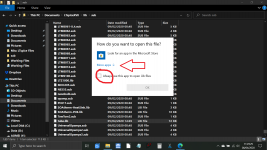
Go to the LT folder and find the tube.lib file you pasted at the beginning of all this.
1/ Right click the file and select 'Open With'
2. UNTICK the box marked always use this app to open .lib
3/ Then click 'More apps' which I have arrowed and scroll down and select 'Notepad' and OK.
That will open the file.
4/ Look at the structure and how models are separated.
5/ Paste your lines of new code in at the end maintaining the same kind of structure.
6/ Save the file using 'File' up at the top left corner and then close it.
Check that the file is still a .lib when you look. This is why unticking that box was important.
-----------------
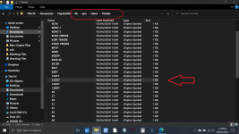
7 Now look at the folder you pasted into the Sym folder that contains the models.
I would guess that as long as the models used conform to the same pinouts then you could resave a model file as a new name (valve number) that exactly matches how it appears in the text file of models. If you click a model it will open in LT. You can then save it by giving it a new name and specifying the correct location (which is where it is now)
I'd have to do all this for real but that would be my first guess how to do it.
Go to the LT folder and find the tube.lib file you pasted at the beginning of all this.
1/ Right click the file and select 'Open With'
2. UNTICK the box marked always use this app to open .lib
3/ Then click 'More apps' which I have arrowed and scroll down and select 'Notepad' and OK.
That will open the file.
4/ Look at the structure and how models are separated.
5/ Paste your lines of new code in at the end maintaining the same kind of structure.
6/ Save the file using 'File' up at the top left corner and then close it.
Check that the file is still a .lib when you look. This is why unticking that box was important.
-----------------
7 Now look at the folder you pasted into the Sym folder that contains the models.
I would guess that as long as the models used conform to the same pinouts then you could resave a model file as a new name (valve number) that exactly matches how it appears in the text file of models. If you click a model it will open in LT. You can then save it by giving it a new name and specifying the correct location (which is where it is now)
I'd have to do all this for real but that would be my first guess how to do it.
Attachments
Great. I'll have a shot at that later. I'm experiencing some screen burn-out this morning. 12 hour sessions, eating on the fly, for a week is no joke. Thanks again.I would guess that as long as the models used conform to the same pinouts then you could resave a model file as a new name (valve number) that exactly matches how it appears in the text file of models. If you click a model it will open in LT. You can then save it by giving it a new name and specifying the correct location (which is where it is now)
I'd have to do all this for real but that would be my first guess how to do it.
By 'models' above in the last paragraph I mean the symbols of the models that are in the SYM folder under Tubes.
So I open a symbol for a triode I know and I would think you could then resave that symbol with a new name to match your text model file. Same for other varieties such as diodes and pentodes. Pick a similar outline and resave it in the correct folder with an appropriate name match to the model.
But... I would need test all this for real 😀
Attachments
Great. I'll have a shot at that later. I'm experiencing some screen burn-out this morning. 12 hour sessions, eating on the fly, for a week is no joke. Thanks again.
OK, that is a long session, the screen will be going low emission at this rate 😀
Its getting toward feeding time here anyway 🙂
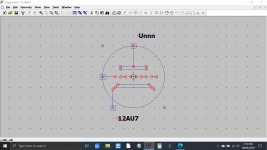
That worked perfectly, thanks. I edited the valve name part of the character string immediately following ".subckt" in the "tube.lib" file to read "Ayumi6SN7". I then copied out the existing 6SN7 ".asy" symbol file onto the desktop and renamed it "Ayumi6SN7", and plonked it into the same folder. So the Ayumi version of the 6SN7 is unambiguously invoked when I need it.I would guess that as long as the models used conform to the same pinouts then you could resave a model file as a new name (valve number) that exactly matches how it appears in the text file of models. If you click a model it will open in LT. You can then save it by giving it a new name and specifying the correct location (which is where it is now)
I'd have to do all this for real but that would be my first guess how to do it.
And - I went one further. To my surprise, .asy files open in LTSpice's symbol editor, and with that, I was able to change the name string to AY6SN7 for further affirmation of the correct choice of valve. And - and I even increased the text size as it would appear on the simulation, because the original was far too small. Looks like you can do quite a lot in that symbol editor, including making your own symbols. I hope I got everything right in this long-winded explanation.
How to improve simulation speed when it takes a long time to complete:
https://electronics.stackexchange.com said:When you hit escape during a stalled DC simulation in LTSpice, the simulator progresses to the next solution method. The first method is direct Newton-Raphson iteration. If that fails, LTSpice will try the following strategies in order by default:
- Adaptive gmin stepping
- Adaptive source stepping
- "Pseudo Transient"
From your screen shot, it looks like you are still hung up when you get to adaptive source stepping. My guess is that when you hit escape at that point, you progress to the Pseudo Transient method and get convergence relatively quickly thereafter. I see this a lot.
If you know which method is converging well for your circuit and you are confident in the results, then you can avoid baysitting your sim by presenting .options directives that disable the methods that are bound to hang up. From the LTSPice manual, the specific directives are:
- Direct Newton Iteration: .options NoOpIter
- Adaptive Gmin Stepping: .options GminSteps=0
- Adaptive Source Stepping: .options SrcSteps=0
- Pseudo Transient: .options pTranTau=0
That is very useful, thanks. My tube sims can never complete using good old Sir Isaac Newton's method, but I notice that in every case with tubes it settles on one particular alternative, which I can't remember right now but I must check it.How to improve simulation speed when it takes a long time to complete:
How to improve simulation speed when it takes a long time to complete:

My own pedestrian recipe is to assign a weird value to a component I think is the culprit, like 1.01K instead of 1K, and that often helps LT to converge.
That is very useful, thanks. My tube sims can never complete using good old Sir Isaac Newton's method, but I notice that in every case with tubes it settles on one particular alternative, which I can't remember right now but I must check it.
...sorry out of topic I just saw you are in Co.Kerry, I have very nice memories of Dingle and Killarney, I lived in Cork 9 years, say hello to your beautiful country...🙂
Sure, I will. I look out my window here every morning to see if the mountains on the Dingle Peninsula are clearly visible. If they are not, it means it is raining, and if they are, it means it is about to rain - no, only kidding. I hope the great, wonderful and hospitable people of Italy can emerge soon from this terrible pandemic situation - I hope we all can....sorry out of topic I just saw you are in Co.Kerry, I have very nice memories of Dingle and Killarney, I lived in Cork 9 years, say hello to your beautiful country...🙂
Sure, I will. I look out my window here every morning to see if the mountains on the Dingle Peninsula are clearly visible. If they are not, it means it is raining, and if they are, it means it is about to rain - no, only kidding. I hope the great, wonderful and hospitable people of Italy can emerge soon from this terrible pandemic situation - I hope we all can.
lol...I know you are not kidding about raining....me too hope soon Italy will be clear with this situation,....you too and all member here take care and be safe.....all the best
That worked perfectly, thanks. I edited the valve name part of the character string immediately following ".subckt" in the "tube.lib" file to read "Ayumi6SN7". I then copied out the existing 6SN7 ".asy" symbol file onto the desktop and renamed it "Ayumi6SN7", and plonked it into the same folder. So the Ayumi version of the 6SN7 is unambiguously invoked when I need it.
And - I went one further. To my surprise, .asy files open in LTSpice's symbol editor, and with that, I was able to change the name string to AY6SN7 for further affirmation of the correct choice of valve. And - and I even increased the text size as it would appear on the simulation, because the original was far too small. Looks like you can do quite a lot in that symbol editor, including making your own symbols. I hope I got everything right in this long-winded explanation.
That's great
Yes, there is a lot of twists and turns to getting used to LT and a lot of it is practice and trying stuff out. The more you learn and the more you can start to think how to do things... and often there are several ways of achieving that.
It's probably in here somewhere, but I don't really want to go through 200 pages.....
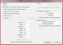
After running a sim, you can left click on a schematic node and the voltage at that node will be tagged to the schematic. Is there any way to do the same with current through a component?
After running a sim, you can left click on a schematic node and the voltage at that node will be tagged to the schematic. Is there any way to do the same with current through a component?
Right click on the voltage text and write the current you wish to display after the dollar sign.
Oops, that doesn't work. Hmm...
Oh, you have to delete the dollar sign.
Oops, that doesn't work. Hmm...
Oh, you have to delete the dollar sign.
Thank you. Now if I can only remember that the next time I need to use itRight click on the voltage text and write the current you wish to display
Just put the cursor over the body of the component and the cursor image will turn from a scope probe to a clamp on current meter.
tommost
tommost
It's probably in here somewhere, but I don't really want to go through 200 pages.....
After running a sim, you can left click on a schematic node and the voltage at that node will be tagged to the schematic. Is there any way to do the same with current through a component?
- Home
- Design & Build
- Software Tools
- Installing and using LTspice IV (now including LTXVII), From beginner to advanced