Builders have a choice: you can believe Rod Elliott, who popularized the R12-C7 circuit, and who said:
Or you can believe diyAudio member Jean-Paul, who says Rod Elliott is wrong.
Your decision. An easy choice.
Note: for a complete view on this matter I asked Rod Elliott for a reaction. Since his website is the modern encyclopedia for audio DIYers it maybe handy to have this schematic explained more clear and the exact use of it.
Rod Elliott replied that the 'efficiency' circuit showed (his version) works perfectly if the components are selected properly. Also that it is not his invention and that it is used in countless products...
Or you can believe diyAudio member Jean-Paul, who says Rod Elliott is wrong.
Your decision. An easy choice.
Elegant to make it personal and ugly.
A. Rod replied that he copied the circuit
B. You stated you copied it from Rod
C. Check the datasheet of the relay YOU choose.
D. If that moron JP would be wrong a reaction would have been enough that he is wrong
E. I did not say Rod is wrong. That is called a lie in my book, sir.
F. saving energy of a 400 mW relay with aforementioned drawbacks is nonsense.
G. "works perfectly if the components are selected properly." is that with current or voltage switching? With ALL relays?
H. I don't know the countless products where it is used. Do you ?
I. You quoted my words")
You make it a kind of political issue where people have to choose Rod or me with even a lie included. I would choose Rod So the choice for a person that is "believable" regardless of what the issue is. It is childish and dirty. Worst is that you maneuvered yourself out of it
While it may work in certain situations with certain relays it is certainly not to be used with every relay. Power saving with relays is done in specific situations with support of the manufacturer and when many are used. I wouldn't like any member to have burned in contacts or the like. It serves no purpose here. That's it. Thanks for taking the time to reply!
A. Rod replied that he copied the circuit
B. You stated you copied it from Rod
C. Check the datasheet of the relay YOU choose.
D. If that moron JP would be wrong a reaction would have been enough that he is wrong
E. I did not say Rod is wrong. That is called a lie in my book, sir.
F. saving energy of a 400 mW relay with aforementioned drawbacks is nonsense.
G. "works perfectly if the components are selected properly." is that with current or voltage switching? With ALL relays?
H. I don't know the countless products where it is used. Do you ?
I. You quoted my words
You make it a kind of political issue where people have to choose Rod or me with even a lie included. I would choose Rod
So the choice for a person that is "believable" regardless of what the issue is. It is childish and dirty. Worst is that you maneuvered yourself out of it While it may work in certain situations with certain relays it is certainly not to be used with every relay. Power saving with relays is done in specific situations with support of the manufacturer and when many are used. I wouldn't like any member to have burned in contacts or the like. It serves no purpose here. That's it. Thanks for taking the time to reply!
Last edited:
Jean Paul, with all respect, I believe you posted your opinions and research, and that is great so that people can make an informed decision. But then, you decided to make it a “truth” that, if no one disputes your answer, everyone is agreeing with you.
I believe it’s good to have different point of views, and people can read and decide one way or the other. From that to issuing “instructions” on what people NEED to do on a design that is not yours, is taking it a bit too far, in my opinion.
Saying “I’d suggest…”, or “if I were building this I would…” is a bit more respectful. Especially considering the source of both the design and the implementation.
Rafa.
Ok no reply or any reaction at all in 6 days. That indicates the information to be correct. ....
Assuming that Cunningham's Law works in your favor is very arrogant. Life is too short to argue everything.
I've had to place several orders to obtain the parts to build a couple of these boards but I still came up short for C3
MKS4J022202D00KSSD WIMA | Mouser United Kingdom
I've checked my spares box and tried all my normal mainstream supplers, including for alternatives, any suggestions?
MKS4J022202D00KSSD WIMA | Mouser United Kingdom
I've checked my spares box and tried all my normal mainstream supplers, including for alternatives, any suggestions?
Ray i have this one in my basket currently. Whether it is any good or not I don't know!
https://www.mouser.co.uk/ProductDetail/Panasonic/ECW-FD2J223KB?qs=BJlw7L4Cy7/v1sRo2IzBEA==
https://www.mouser.co.uk/ProductDetail/Panasonic/ECW-FD2J223KB?qs=BJlw7L4Cy7/v1sRo2IzBEA==
Hi Jim, that cap should do the trick. I actually checked Mouser and saw it but must have focussed on the 'Long Lead Time' message instead of the stock level - another senior moment! Any chance you can grab a couple for me if you're placiing an order? I'll obviously reimburse your costs.
Ray
Ray
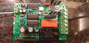
I've been soldering up a couple of these boards this afternoon. A question about the inrush limiter rating if I may.
My power supply is +/-24V. Each channel has a separate bipolar CRC arrangement with 47000F caps and using the info in the OP I've calculated 13joules per cap. With four caps for the positive rails and the same for negative rails that gives a total of about 110joules. Will I be OK with the 125joules rated limiter or should I consider the 250joules version?
My power supply is +/-24V. Each channel has a separate bipolar CRC arrangement with 47000F caps and using the info in the OP I've calculated 13joules per cap. With four caps for the positive rails and the same for negative rails that gives a total of about 110joules. Will I be OK with the 125joules rated limiter or should I consider the 250joules version?
If you decide to install the 250 Joule inrush current limiter, for the extra peace of mind that comes from large margins of safety, remember that you'll have to modify the component yourself, if your AC mains are 230 volts.
The 125 Joule limiter is within its specifications in a 110 Joule application, and ought to work beautifully as long as you avoid "hot restart" events: On / Off / right back On again. On the other hand, the price of the super-robust 250 Joule model is small and the comfort it delivers is large. Your decision.
The drill holes are juuuuust big enough that the "115VAC mains" ICL slides in easily. However the "230VAC mains" ICL has slightly larger diameter leads, so you'll need to reduce them a teeny bit. Sandpaper, needle file, scraping with diagonal cutters, anything you try will probably work. Don't worry, an ICL is not Static Sensitive and it survives an Electro Static Discharge with zero damage. So sand / file / scrape to your heart's content. Just don't drop it onto a hard surface. There's a reason why Mouser and DigiKey pack them individually in bubble wrap
The 125 Joule limiter is within its specifications in a 110 Joule application, and ought to work beautifully as long as you avoid "hot restart" events: On / Off / right back On again. On the other hand, the price of the super-robust 250 Joule model is small and the comfort it delivers is large. Your decision.
Hello all.
Another one is born, and I was going to say it breathes aswell but all is not well!
Initial power up proves the relay and leds are doing the correct things. But when I measure the output I have the same readings even with the board switched off.
I have jumpered for 230v and I see these VACs.
P1D P2D 240
P1D P1N approx 16
P2D P2N approx 6.
Same results with either switched on or off.
I've read the thread a couple times but I havent been able to suss out where I am wrong. Any advice appreciated.
Thanks
Attachments
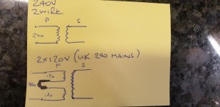
Draw a schematic diagram showing exactly how you'd want all four primary wires to be connected to the mains (or to each other, or both), if there were no H9KPXG involved.
This will make it easy for you to decide, how you'll configure an H9KPXG in order to achieve your desired connections.
This will make it easy for you to decide, how you'll configure an H9KPXG in order to achieve your desired connections.
Thanks Mark. This is very simple but sometimes the simple things trip me up.
So if I had a 2 wire primary 240v trafo I would wire as in the top diagram.
If I had a trafo with 4 wires ( 2 x120v) to wire to UK 240v mains I would wire as the lower diagram.. Black link wire to create series connection.
Thankyou
So if I had a 2 wire primary 240v trafo I would wire as in the top diagram.
If I had a trafo with 4 wires ( 2 x120v) to wire to UK 240v mains I would wire as the lower diagram.. Black link wire to create series connection.
Thankyou
Attachments
- Home
- Amplifiers
- Power Supplies
- PCB: low voltage On-Off switch drives AC mains relay \ includes soft start .. H9KPXG