This PS opens another window in comparison to the standard smps of the Etherregen. There is more space and openness in the sound field. This is a well recommended Upgrade!
Ian isn’t the only one who have discovered the positive effect supercapacitors have in a well designed power supply.
Especially in the lower frequencies it’s easy to hear that supercaps has an advantage over standard caps.
Especially in the lower frequencies it’s easy to hear that supercaps has an advantage over standard caps.
Attachments


Last edited:
That’s nice but does not really impress us. It is only 2F against 325F for one supercapacitor on Ians boards.
The Allo Shanti and Farad 3 ( Farad Power Supplies )
power supplies also use small supercaps in the range of a few F.
The difference with the big 325F caps is that these have a much lower ESR.
I use a UcConditioner on the output of my Shanty PS 😀
The Allo Shanti and Farad 3 ( Farad Power Supplies )
power supplies also use small supercaps in the range of a few F.
The difference with the big 325F caps is that these have a much lower ESR.
I use a UcConditioner on the output of my Shanty PS 😀
LinearPi also addressed the MLCC piezoelectric effect, which picks mechanical vibration and generates noise to the voltage rails.
Many current low noise power supply designs didn't take this issue into consideration. It will degrade the ultra-low noise performance. Has any body seen the MLCC piezoelectric effect over voltage rails before?
Regards,
Ian
Many current low noise power supply designs didn't take this issue into consideration. It will degrade the ultra-low noise performance. Has any body seen the MLCC piezoelectric effect over voltage rails before?
Regards,
Ian
Yes, it is a feature coming for free with ceramic SMD capacitors but varies strongly depending on brand and type. It is certainly taken in consideration in the industry and at manufacturers. Incidentally I found a rail Panasonic SMD MKT capacitors yesterday. These did not have this phenomenon as much but they were taken out of production as happens to many good quality parts.
As a DIYer I have to use the means that are in my reach. Choosing the better SMD caps helps, a coating with plastic spray for electronics helps. Epoxy also helps but repair is impossible and heat is a no no.
Regarding supercaps: of course I noticed the hype around super capacitors and using extreme amounts of Farads. I absolutely believe it makes things better but my question is what happens when a failure occurs in such a cap with that amounts of energy available. Do you have any experience when one fails? My assumption (dangerous, I know) is that it will cause an explosion and/or irreparable damage.
Secondly, how is the power off behaviour when using such vast amounts of capacitance? I have at least 1 device that does not like slowly discharging PSU's.
BTW we can look with extremely sharp eyes to PSU's but the RPI itself for course has the cheapest ceramic SMD caps available 😀 If we would look at it with the same eyes we would probably use another source made specifically for audio purposes.
Last edited:
Hi Jean-Paul
As an anecdotal observation, I can say that the wireless networking company I worked for was an early adapter of supercaps using 50F caps as a UPS for remote radio sensors. They were installed in several million devices and have run for a decade in the field without issue. Our biggest failure mode was due to improper installation. They had radial leads. If you bend the leads at the cap surface it leads to a leakage of the electrolyte which will cause the leads corrode and fail over time. They literally evaporate causing an open circuit.
I use some of these older Nesscaps in the various PS in my DAC with success.
Your point about safety is important. And they are a pain due to the slow discharge on power off.
I have no experience with the 300F monsters being used by most on this thread. Can only urge people to handle with care.
Thanks. It is my experience with large battery installations that made me think of the risks involved. For this reason I would not install batteries (for solar energy) in normal homes. Having energy in abundance is nice till something goes wrong.
A very long time ago I used Sanyo (I think as they had a green sleeve) supercaps but these were prone to failure and as they had the tendency to leak the aggressive electrolyte destroyed the board. When I read about recent supercapacitors I also noticed that they still have low voltage ratings, a reason why they are used in series. So when either one fails they will blow both (again suspicion based on battery experiences). I then decided not to start designing with these until 16V or 25V versions would come but they are not around.
The amount of energy needed to charge them, the need to bleed them at power off, the slowly decaying output voltage that many devices don't accept. All can be solved probably but things are then complicated. They are very interesting parts, maybe I should experiment with them. The Farad 3 PSU is highly regarded and it uses them too.
In the DIY field it is probably very wise to always install these in a sturdy metal casing, use thicker PCB material and have the boards mounted to the casing with M4 metal standoffs.
Last edited:
Hello,
It a good thing to realize that these ultracaps can be dangerous and there are some serious things to consider before using them.
Thr French used them in the past when they were very mediocre compared to ordinary caps regarding internal resistance. The reason for using them i believe was to reduce the overall ripple in the power supply. That time time they were something like 1F maximum and ehen used for a power amp they would go empty rather quick.
But here they are used for things that draw minimal current and like Jean Paul said like their power supplies to drain pretty quick.
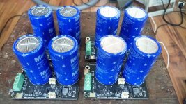
Knowing the DIY community well it would take long before people start mounting a handful of these caps on a wooden board.
Maybe there should be a sticky could be as dangerous as a high voltage supply.
Greetings, Eduard
It a good thing to realize that these ultracaps can be dangerous and there are some serious things to consider before using them.
Thr French used them in the past when they were very mediocre compared to ordinary caps regarding internal resistance. The reason for using them i believe was to reduce the overall ripple in the power supply. That time time they were something like 1F maximum and ehen used for a power amp they would go empty rather quick.
But here they are used for things that draw minimal current and like Jean Paul said like their power supplies to drain pretty quick.
Knowing the DIY community well it would take long before people start mounting a handful of these caps on a wooden board.
Maybe there should be a sticky could be as dangerous as a high voltage supply.
Greetings, Eduard
You read my mind when you mentioned "wooden board" 😀 No standoffs and melt glue are next level.
@nagini, depends on what you will connect them to. Ultracaps won't filter hf noise, so if your chosen switching supplies or the client device doesn't have good local filtering for it, you can expect it to pass through.
@Raj1: so I must use the ultra low noise linear power supply for input to get the best output?
Need help !!
I have two 5v Ucconditioner board that I want to connect in series to get 10v on output, but the conditioners suck the life out of my two doede dac psu’s which is rated 1A each, is this simply not enough current, or am I missing something ?
No problem with 5v input on each conditioner separatly.
I have two 5v Ucconditioner board that I want to connect in series to get 10v on output, but the conditioners suck the life out of my two doede dac psu’s which is rated 1A each, is this simply not enough current, or am I missing something ?
No problem with 5v input on each conditioner separatly.
Last edited:
Need help !!
I have two 5v Ucconditioner board that I want to connect in series to get 10v on output, but the conditioners suck the life out of my two doede dac psu’s which is rated 1A each, is this simply not enough current, or am I missing something ?
No problem with 5v input on each conditioner separatly.
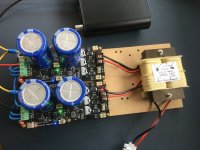
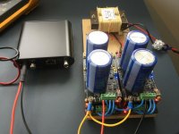
You cannot connect then in series to a 10v input. They need to be fed separately with galvanic isolated 5v power supplies and than you can connect the output in series for 10v.
I did it like this:
Attachments
Yes, when I separate the two dddac’s psu’s, it works fine. The mistake I did was to run dddac’s psu’s wired together in parallel
Last edited:
You cannot connect then in series to a 10v input. They need to be fed separately with galvanic isolated 5v power supplies and than you can connect the output in series for 10v.
What other LPSs have you tried with your EtherRegen, and how did each of their sound signatures compare to your 10V series connection?
- Home
- Amplifiers
- Power Supplies
- Develop ultra capacitor power supply and LiFePO4 battery power supply