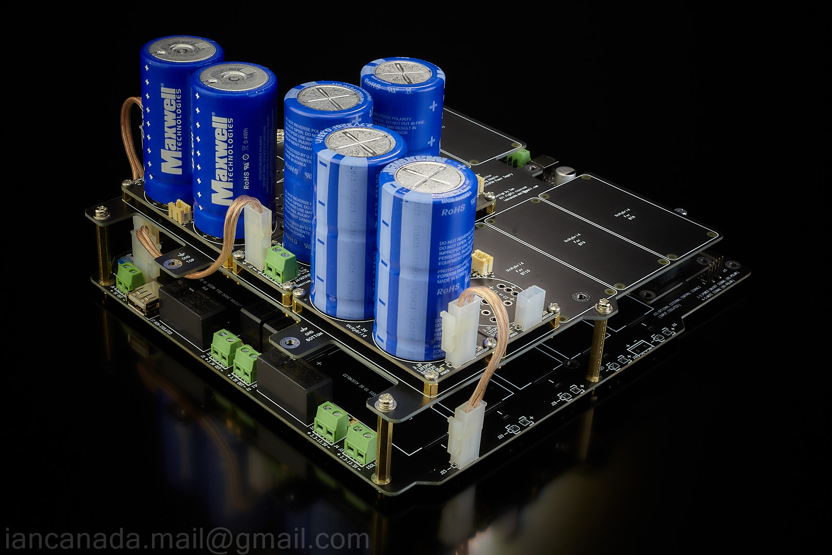
New LifePO4 power supply MKIII was fully tested without problem.
The improvements to the MKII are:
1. Ready upgrading to ultra capacitor power supply by integrating with UcMateConditioner and UcHybrid.
2. New continuous DC 5V mode can be enabled now.
3. PTC fuses replace the protection resistors to reduce the risk of possible damaging and reworking.
4. New optimized PCB layout and the double thickness copper layers lower the power supply ESR even more.
5. Accuracy of voltage measurements and monitoring were increased.
6. Can have up to six outputs of 3.3V LifePO4 voltage rails in total.
PCB size was increased a little bit but all mounting holes are still compatible with MKII.
Ian
That is very cool! When can we order these together with the ultra capacitor board?
Regards,
That is very cool! When can we order these together with the ultra capacitor board?
Regards,
I will place an order for this too once ready
Upgrading the LifePO4 MKIII to ultra capacitor power supply
Upgrading the LifePO4 MKIII to ultra capacitor power supply would be very easy and flexible. Just need UcMateConditioner (for 5V) and UcHybrid (for 3.3V rails). UcAdapter board will be optional to mount all of them together as well as additional shield layers.
To link them together we just need a bridge cable for each board. Cable should be short and big to keep the lowest ESR performance. It's also no problem to upgrade with MKII. Just need to solder the other side of the UcHybard bridge cable directly to the battery pads of PCB rather than connectors.
BXAP0325 P270 S17 is the lowest ESR UC so far. Other suitable size Maxwell Nesscap UCs also work. It could be the best power supply that can be reached so far with this crazy upgrading.

LifePO4MKIII5 by Ian, on Flickr

UcMateConditionerUcHybridUcAdapter by Ian, on Flickr
UcIntegaration1 by Ian, on Flickr

UcIntegaration2 by Ian, on Flickr
Ian
Upgrading the LifePO4 MKIII to ultra capacitor power supply would be very easy and flexible. Just need UcMateConditioner (for 5V) and UcHybrid (for 3.3V rails). UcAdapter board will be optional to mount all of them together as well as additional shield layers.
To link them together we just need a bridge cable for each board. Cable should be short and big to keep the lowest ESR performance. It's also no problem to upgrade with MKII. Just need to solder the other side of the UcHybard bridge cable directly to the battery pads of PCB rather than connectors.
BXAP0325 P270 S17 is the lowest ESR UC so far. Other suitable size Maxwell Nesscap UCs also work. It could be the best power supply that can be reached so far with this crazy upgrading.
LifePO4MKIII5 by Ian, on Flickr
UcMateConditionerUcHybridUcAdapter by Ian, on Flickr
UcIntegaration1 by Ian, on Flickr
UcIntegaration2 by Ian, on Flickr
Ian
@aguaazul
Yes, it is possible to include this new continuous DC 5V feature to MKII by upgrading the firmware.
Regards,
Ian
Good news !
Could u explain us how?
I also understood that we can use the conditioner’s boards also with MKII version of LiFePO4.
We need detailed instructions to do this. Are you planning to insert these instructions into the manual of the boards or can you publish something here ?
Last but not least, when the GB?
In this period of COVID we have time to dedicate to your stuff
")
Really interesting board... I never use the battery supply so I have no experience but I read carefully the thread and I become to the decision that the battery PSU & supercap will be my next upgrade to my dac.
As far I understand, the get the best performance, the local LDO should be bypassed. The big doubt that I have is relevant to the local LDOs for the analog side that are settled at 8V. Would be possible to get the same voltage from the MKIII?
Thanks and Regards,
Enrico
As far I understand, the get the best performance, the local LDO should be bypassed. The big doubt that I have is relevant to the local LDOs for the analog side that are settled at 8V. Would be possible to get the same voltage from the MKIII?
Thanks and Regards,
Enrico
If you want to stay with pure battery power then you are limited to multiples of 3.3V. the closest voltage will be 9.9V. If what you want to power can tolerate this variance, you're good to go. Otherwise you can apply regulation to achieve the required voltage by using for example the Ldover LT3045 boards so long as you don't need high current. This still gives the benefit if isolation but adds regulator noise. I have ordered a couple of boards to get to 5V but as not installed, cannot offer any experience on results.
Martin
Martin
Martin, thanks for your reply.
I already have 2 LDO LT1762 on my design, one for the digital side (3.3V) and one for the analog (8V) and as per datasheet I am already at the limit of the Vmax in the analog side.
As I said I have no experience/knowledge on batteries and I was "hoping" that we can, through the charge/discharge control, limit the voltage to 2.7V to get the 8.1V isolated and bypass the LDOs.
If that is not possible I have 2 way to experiment... keep the LT on board and use 3 batteries at 9.9V or remove the LT and power the chip at 6.6V
Cheers,
Enrico
Attachments
Typical 37mA, Max 40mA
That seems very low and I noticed Ian is note stating the current outputs unless I missed it?
Typical 37mA, Max 40mA
Just to check...this for Ian Canada’s LiFePO4 battery power supply, rather than your own design?
- Home
- Amplifiers
- Power Supplies
- Develop ultra capacitor power supply and LiFePO4 battery power supply