The Shanti has 3.5A current output for the Pi and 1.5A for the DAC both with 2x3F supercaps on the output. 0.08 uV ripple.
The LT 3045 has max 500mA.
The LT 3045 has max 500mA.
I'd struggle to build anything the price of the Shanti, I could barely put 7 lt3045 and a transformer in the case for the same price.
Total solution: UcMateConditioner + UcHybrid + UcAdapter
I'm busy working on the ultra capacitor upgrade total solution, which are:
1. UcMateConditioner (5V)
2. UcHybrid (3,3V each, capable for 13.2V when more boards are used)
3. UcAdapter PCB
This total solution will work seamlessly for LifePO4 MKIII. It can also work for MKII. The screw positions may not match MKI very well.
UcAdapter PCB will be installed on top of LiefPO4 MKIII or MKII.
UcAdapter PCB also has two shield layers.
More update will be posted soon.

UcUpgradeSolution2 by Ian, on Flickr

UcUpgradeSolution1 by Ian, on Flickr
Ian
I'm busy working on the ultra capacitor upgrade total solution, which are:
1. UcMateConditioner (5V)
2. UcHybrid (3,3V each, capable for 13.2V when more boards are used)
3. UcAdapter PCB
This total solution will work seamlessly for LifePO4 MKIII. It can also work for MKII. The screw positions may not match MKI very well.
UcAdapter PCB will be installed on top of LiefPO4 MKIII or MKII.
UcAdapter PCB also has two shield layers.
More update will be posted soon.
UcUpgradeSolution2 by Ian, on Flickr
UcUpgradeSolution1 by Ian, on Flickr
Ian
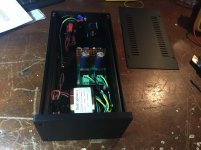
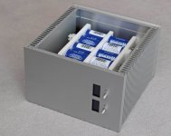
Seeing Ian's progress has prompted me to post my take on his battery/ultracap combo. This is now up and running and the ultracaps add texture to the bass, especially cellos. This supplies power to the M Scaler for two hours when fully charged at 13V. I have another battery board (damaged) that Ian has offered to repair that will double run time. Once I get this sorted, I will box it all up in a Takachi case; a very tight fit. Photo of box doesn't show top board added.
Attachments

Hi Ian,
Your UC solution looks interesting. From your testing indicating short distances and thick wires are best between the batteries and UCs, I thought you may have exploited the opportunity to direct connect the UC board to the battery board using headers and footers to the slots connecting the batteries on the battery board.
Martin.
Seeing Ian's progress has prompted me to post my take on his battery/ultracap combo. This is now up and running and the ultracaps add texture to the bass, especially cellos. This supplies power to the M Scaler for two hours when fully charged at 13V. I have another battery board (damaged) that Ian has offered to repair that will double run time. Once I get this sorted, I will box it all up in a Takachi case; a very tight fit. Photo of box doesn't show top board added.
@hibo4
You integration looks awesome, Very professional! You did good job!
Did you pre-charge each ultra capacitors?
Regards,
Ian
Hi Ian,
Charging the UCs was both simpler and more difficult than expected. My Plan was to connect the empty battery board and charge each set with the lifepo charger I have. Unfortunately, the charger couldn't see any batteries so I charged them with a 3.3V power supply. Once the UCs had a couple of volts, I could revert to the charger. What surprised me was that all the UCs charged together. The process took about three hours.
Martin
Seeing Ian's progress has prompted me to post my take on his battery/ultracap combo. This is now up and running and the ultracaps add texture to the bass, especially cellos. This supplies power to the M Scaler for two hours when fully charged at 13V. I have another battery board (damaged) that Ian has offered to repair that will double run time. Once I get this sorted, I will box it all up in a Takachi case; a very tight fit. Photo of box doesn't show top board added.
Amazing work!
Agreed. Beautiful work on the case BTW. Your comments wrt the sound of a cello resonates with me.
Hi Ian,
This looks promising.
How will the connection to the battery board be made? As short and thick leads are important to get the best out of the super low impedance of the supercaps, this seems to me one of the most important design choices.
Would it not be better to put this board up side down below the battery board so very short leads are possible?
Regards,
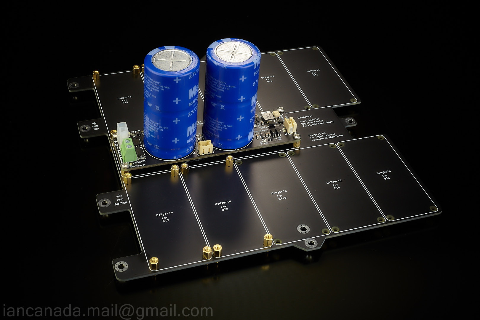
UcMateConditioner
Functionally UcMateConditioner is exactly as same as UcConditioner. The difference is that it was designed dedicated to the LifePO4 power supply through UcAdapter PCB. It works directly with MKIII, as well as MKII.
UcMateConditioner uses low ESR MOS FETs rather than the relays to improve the performance. By connecting to the control signal from the LifePO4 power supply board, they will work together seamlessly.
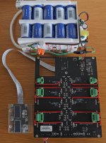
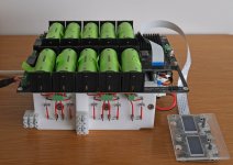
The first picture is the UcMateConditoner boards.
The second picture is how it is mounted it to the UcAdapter PCB
Maxwell/NESSCAP BCAP0325 P270 S17 is confirmed to be the best performance because of the lowest ESR so far. Other ultra capacitors can also be used, such as BACP0350 E270 T11.
UcAdapter PCB will be installed on top of the LifePO4 power supply. It also has double shield layers.

UcMateConditioner1 by Ian, on Flickr
UcMateConditionerUcAdapter by Ian, on Flickr
Ian
Functionally UcMateConditioner is exactly as same as UcConditioner. The difference is that it was designed dedicated to the LifePO4 power supply through UcAdapter PCB. It works directly with MKIII, as well as MKII.
UcMateConditioner uses low ESR MOS FETs rather than the relays to improve the performance. By connecting to the control signal from the LifePO4 power supply board, they will work together seamlessly.
The first picture is the UcMateConditoner boards.
The second picture is how it is mounted it to the UcAdapter PCB
Maxwell/NESSCAP BCAP0325 P270 S17 is confirmed to be the best performance because of the lowest ESR so far. Other ultra capacitors can also be used, such as BACP0350 E270 T11.
UcAdapter PCB will be installed on top of the LifePO4 power supply. It also has double shield layers.
UcMateConditioner1 by Ian, on Flickr
UcMateConditionerUcAdapter by Ian, on Flickr
Ian
Last edited:
@paoloilpizzo
I'm working on a couple of projects now.
1. LifePO4 MKIII
2. UcMateConditioner (5V)
3. UcHybrid (3.3V, capable for higher voltage if use more)
4. UcAdapter PCB
5. ConditionerPi (5V)
5. UcConditioner (5V)
I'm trying my best to make them available soon.
Ian
I'm working on a couple of projects now.
1. LifePO4 MKIII
2. UcMateConditioner (5V)
3. UcHybrid (3.3V, capable for higher voltage if use more)
4. UcAdapter PCB
5. ConditionerPi (5V)
5. UcConditioner (5V)
I'm trying my best to make them available soon.
Ian
@paoloilpizzo
I'm working on a couple of projects now.
1. LifePO4 MKIII
2. UcMateConditioner (5V)
3. UcHybrid (3.3V, capable for higher voltage if use more)
4. UcAdapter PCB
5. ConditionerPi (5V)
5. UcConditioner (5V)
I'm trying my best to make them available soon.
Ian
thank you !!
imagine that there are several such boards. will it be possible to control on and off centrally? Is there a mechanism and solutions for this?
@paoloilpizzo
I'm working on a couple of projects now.
1. LifePO4 MKIII
2. UcMateConditioner (5V)
3. UcHybrid (3.3V, capable for higher voltage if use more)
4. UcAdapter PCB
5. ConditionerPi (5V)
5. UcConditioner (5V)
I'm trying my best to make them available soon.
Ian
Hello, Ian.
I'd like to PM, but you have to many messages 🙂
Hello, Ian.
I'd like to PM, but you have to many messages 🙂
Sorry, my message box was full. I need to make another donation before I can read your message.
Regards,
LifePO4 power supply MKIII
New LifePO4 power supply MKIII was fully tested without problem.
The improvements to the MKII are:
1. Ready upgrading to ultra capacitor power supply by integrating with UcMateConditioner and UcHybrid.
2. New continuous DC 5V mode can be enabled now.
3. PTC fuses replace the protection resistors to reduce the risk of possible damaging and reworking.
4. New optimized PCB layout and the double thickness copper layers lower the power supply ESR even more.
5. Accuracy of voltage measurements and monitoring were increased.
6. Can have up to six outputs of 3.3V LifePO4 voltage rails in total.
PCB size was increased a little bit but all mounting holes are still compatible with MKII.

LifePO4MKIII1 by Ian, on Flickr

LifePO4MKIII2 by Ian, on Flickr

LifePO4MKIII3 by Ian, on Flickr
Pleas do take care under this COVID19 situation!
Ian
New LifePO4 power supply MKIII was fully tested without problem.
The improvements to the MKII are:
1. Ready upgrading to ultra capacitor power supply by integrating with UcMateConditioner and UcHybrid.
2. New continuous DC 5V mode can be enabled now.
3. PTC fuses replace the protection resistors to reduce the risk of possible damaging and reworking.
4. New optimized PCB layout and the double thickness copper layers lower the power supply ESR even more.
5. Accuracy of voltage measurements and monitoring were increased.
6. Can have up to six outputs of 3.3V LifePO4 voltage rails in total.
PCB size was increased a little bit but all mounting holes are still compatible with MKII.
LifePO4MKIII1 by Ian, on Flickr
LifePO4MKIII2 by Ian, on Flickr
LifePO4MKIII3 by Ian, on Flickr
Pleas do take care under this COVID19 situation!
Ian
Last edited:
Ian,
Is there any possibility that the MKII's could get the firmware upgrade to enable the "Continuous DC 5V"?
As always... thanks for all you do for us!!
Aguaazul
Is there any possibility that the MKII's could get the firmware upgrade to enable the "Continuous DC 5V"?
As always... thanks for all you do for us!!
Aguaazul
The improvements to the MKII are:
2. New continuous DC 5V mode can be enabled now.
- Home
- Amplifiers
- Power Supplies
- Develop ultra capacitor power supply and LiFePO4 battery power supply